<< Chapter < Page Chapter >> Page >
By the end of this section, you will be able to:
  • Describe Huygens’s principle
  • Use Huygens’s principle to explain the law of reflection
  • Use Huygens’s principle to explain the law of refraction
  • Use Huygens’s principle to explain diffraction

So far in this chapter, we have been discussing optical phenomena using the ray model of light. However, some phenomena require analysis and explanations based on the wave characteristics of light. This is particularly true when the wavelength is not negligible compared to the dimensions of an optical device, such as a slit in the case of diffraction . Huygens’s principle is an indispensable tool for this analysis.

[link] shows how a transverse wave looks as viewed from above and from the side. A light wave can be imagined to propagate like this, although we do not actually see it wiggling through space. From above, we view the wave fronts (or wave crests) as if we were looking down on ocean waves. The side view would be a graph of the electric or magnetic field. The view from above is perhaps more useful in developing concepts about wave optics    .

Three figure contains three views of a wave.  The first is a view from above. The wave is propagating to the right, and appears as a series of vertical strips that gradually alternate from dark to light and repeat. The next view is a view from the side. The wave again propagates to the right and appears as a sine curve oscillating above and below a black arrow pointing to the right that serves as the horizontal axis. The third is an overall view. This is a perspective view of a wave of the same wavelength as in the first two images and looks like an undulating surface..
A transverse wave, such as an electromagnetic light wave, as viewed from above and from the side. The direction of propagation is perpendicular to the wave fronts (or wave crests) and is represented by a ray.

The Dutch scientist Christiaan Huygens (1629–1695) developed a useful technique for determining in detail how and where waves propagate. Starting from some known position, Huygens’s principle    states that every point on a wave front is a source of wavelets that spread out in the forward direction at the same speed as the wave itself. The new wave front is tangent to all of the wavelets.

[link] shows how Huygens’s principle is applied. A wave front is the long edge that moves, for example, with the crest or the trough. Each point on the wave front emits a semicircular wave that moves at the propagation speed v . We can draw these wavelets at a time t later, so that they have moved a distance s = v t . The new wave front is a plane tangent to the wavelets and is where we would expect the wave to be a time t later. Huygens’s principle works for all types of waves, including water waves, sound waves, and light waves. It is useful not only in describing how light waves propagate but also in explaining the laws of reflection and refraction. In addition, we will see that Huygens’s principle tells us how and where light rays interfere.
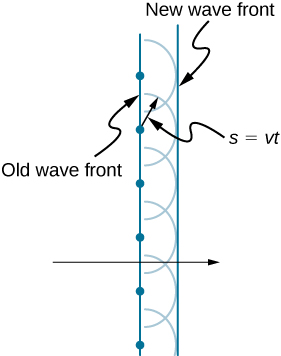
This figure shows two straight vertical lines, with the left line labeled old wave front and the right line labeled new wave front. In the center of the image, a horizontal black arrow crosses both lines and points to the right. The old wave front line passes through six evenly spaced dots, with four dots above the black arrow and four dots below the black arrow. Each dot serves as the center of a corresponding semicircle, and all eight semicircles are the same size. The new wave front is tangent to the right edge of the semicircles.  One of the center dots has a radial arrow pointing to a point on the corresponding semicircle. This radial arrow is labeled s equals v t.
Huygens’s principle applied to a straight wave front. Each point on the wave front emits a semicircular wavelet that moves a distance s = v t . The new wave front is a line tangent to the wavelets.

Reflection

[link] shows how a mirror reflects an incoming wave at an angle equal to the incident angle, verifying the law of reflection. As the wave front strikes the mirror, wavelets are first emitted from the left part of the mirror and then from the right. The wavelets closer to the left have had time to travel farther, producing a wave front traveling in the direction shown.
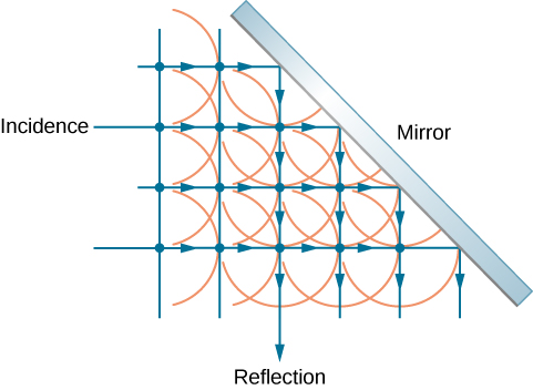
The figure shows a grid of four horizontal, parallel, equally spaced rays incident on a mirror that is tilted at forty five degrees to the rays. The rays reflect downward from the mirror. Two additional reflected rays are included from incident rays above those shown in the figure. Dots are drawn at the intersections of incident and reflected rays. Semicircles facing to the right representing incident wavelets and semicircles facing down for reflecting wavelets are centered on the dots.
Huygens’s principle applied to a plane wave front striking a mirror. The wavelets shown were emitted as each point on the wave front struck the mirror. The tangent to these wavelets shows that the new wave front has been reflected at an angle equal to the incident angle. The direction of propagation is perpendicular to the wave front, as shown by the downward-pointing arrows.
Practice Key Terms 2

Get Jobilize Job Search Mobile App in your pocket Now!

Get it on Google Play Download on the App Store Now


Source:  OpenStax, University physics volume 3. OpenStax CNX. Nov 04, 2016 Download for free at http://cnx.org/content/col12067/1.4
Google Play and the Google Play logo are trademarks of Google Inc.

Notification Switch

Would you like to follow the 'University physics volume 3' conversation and receive update notifications?

Ask