| << Chapter < Page | Chapter >> Page > |
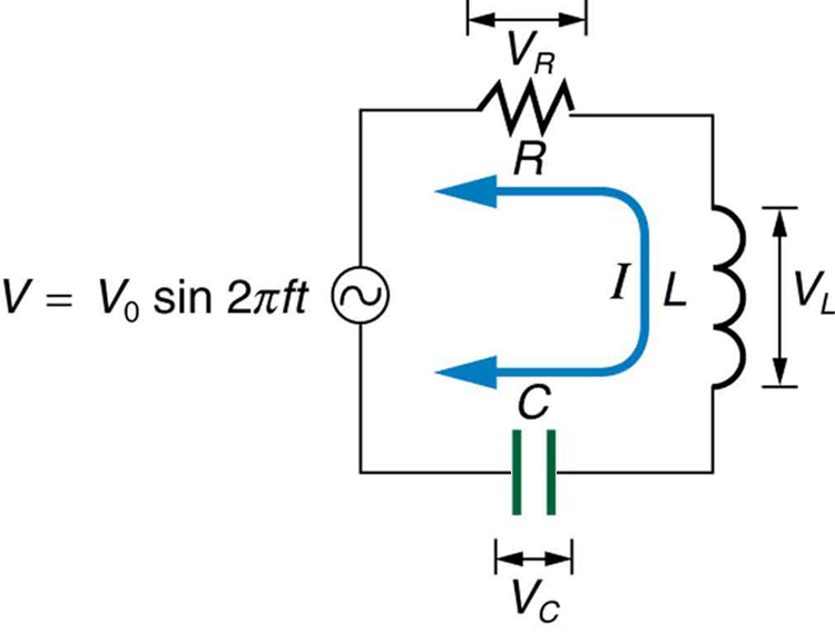
When alone in an AC circuit, inductors, capacitors, and resistors all impede current. How do they behave when all three occur together? Interestingly, their individual resistances in ohms do not simply add. Because inductors and capacitors behave in opposite ways, they partially to totally cancel each other’s effect. [link] shows an RLC series circuit with an AC voltage source, the behavior of which is the subject of this section. The crux of the analysis of an RLC circuit is the frequency dependence of and , and the effect they have on the phase of voltage versus current (established in the preceding section). These give rise to the frequency dependence of the circuit, with important “resonance” features that are the basis of many applications, such as radio tuners.

The combined effect of resistance , inductive reactance , and capacitive reactance is defined to be impedance , an AC analogue to resistance in a DC circuit. Current, voltage, and impedance in an RLC circuit are related by an AC version of Ohm’s law:
Here is the peak current, the peak source voltage, and is the impedance of the circuit. The units of impedance are ohms, and its effect on the circuit is as you might expect: the greater the impedance, the smaller the current. To get an expression for in terms of , , and , we will now examine how the voltages across the various components are related to the source voltage. Those voltages are labeled , , and in [link] .
Conservation of charge requires current to be the same in each part of the circuit at all times, so that we can say the currents in , , and are equal and in phase. But we know from the preceding section that the voltage across the inductor leads the current by one-fourth of a cycle, the voltage across the capacitor follows the current by one-fourth of a cycle, and the voltage across the resistor is exactly in phase with the current. [link] shows these relationships in one graph, as well as showing the total voltage around the circuit , where all four voltages are the instantaneous values. According to Kirchhoff’s loop rule, the total voltage around the circuit is also the voltage of the source.
You can see from [link] that while is in phase with the current, leads by , and follows by . Thus and are out of phase (crest to trough) and tend to cancel, although not completely unless they have the same magnitude. Since the peak voltages are not aligned (not in phase), the peak voltage of the source does not equal the sum of the peak voltages across , , and . The actual relationship is
where , , and are the peak voltages across , , and , respectively. Now, using Ohm’s law and definitions from Reactance, Inductive and Capacitive , we substitute into the above, as well as , , and , yielding

Notification Switch
Would you like to follow the 'College physics ii' conversation and receive update notifications?