| << Chapter < Page | Chapter >> Page > |
The magnetic field of a long straight wire has more implications than you might at first suspect. Each segment of current produces a magnetic field like that of a long straight wire, and the total field of any shape current is the vector sum of the fields due to each segment. The formal statement of the direction and magnitude of the field due to each segment is called the Biot-Savart law . Integral calculus is needed to sum the field for an arbitrary shape current. This results in a more complete law, called Ampere’s law , which relates magnetic field and current in a general way. Ampere’s law in turn is a part of Maxwell’s equations , which give a complete theory of all electromagnetic phenomena. Considerations of how Maxwell’s equations appear to different observers led to the modern theory of relativity, and the realization that electric and magnetic fields are different manifestations of the same thing. Most of this is beyond the scope of this text in both mathematical level, requiring calculus, and in the amount of space that can be devoted to it. But for the interested student, and particularly for those who continue in physics, engineering, or similar pursuits, delving into these matters further will reveal descriptions of nature that are elegant as well as profound. In this text, we shall keep the general features in mind, such as RHR-2 and the rules for magnetic field lines listed in Magnetic Fields and Magnetic Field Lines , while concentrating on the fields created in certain important situations.
Hearing all we do about Einstein, we sometimes get the impression that he invented relativity out of nothing. On the contrary, one of Einstein’s motivations was to solve difficulties in knowing how different observers see magnetic and electric fields.
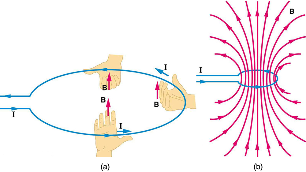
The magnetic field near a current-carrying loop of wire is shown in [link] . Both the direction and the magnitude of the magnetic field produced by a current-carrying loop are complex. RHR-2 can be used to give the direction of the field near the loop, but mapping with compasses and the rules about field lines given in Magnetic Fields and Magnetic Field Lines are needed for more detail. There is a simple formula for the magnetic field strength at the center of a circular loop . It is
where is the radius of the loop. This equation is very similar to that for a straight wire, but it is valid only at the center of a circular loop of wire. The similarity of the equations does indicate that similar field strength can be obtained at the center of a loop. One way to get a larger field is to have loops; then, the field is . Note that the larger the loop, the smaller the field at its center, because the current is farther away.


Notification Switch
Would you like to follow the 'Basic physics for medical imaging' conversation and receive update notifications?