| << Chapter < Page | Chapter >> Page > |
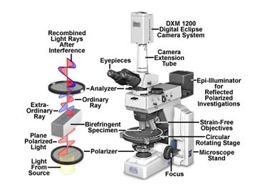
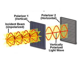
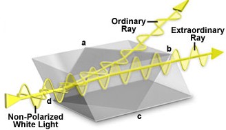
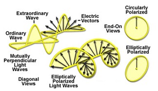
Birefringent or doubly-refracting sample has a unique property that it can produce two individual wave components while one wave passes through it, those two components are termed as ordinary and extraordinary waves. [link] is an illustration of a typical construction of Nicol polarizing prism, as we can see, the non-plarized white light are splitted into two ray as it passes through the prism. The one travels out of the prism is called ordinary ray, and the other one is called extraordinary ray. So if we have a birefringent specimen located between the polarizer and analyzer, the initial light will be separated into two waves when it passes though the specimen. After exiting the specimen, the light components become out of phase, but are recombined with constructive and destructive interference when they pass through the analyzer. Now the combined wave will have elliptically or circularly polarized light wave, see [link] , image contrast arises from the interaction of plane-polarized light with a birefringent specimen so some amount of wave will pass through the analyzer and give a bright domain on the specimen.
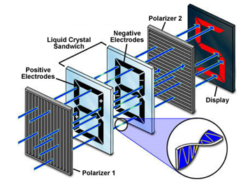
The most common application of LCs are in liquid crystals displays (LCD). [link] is a simple demonstration of how LCD works in digit calculators. There are two crossed polarizers in this system, and liquid crystal (cholesteric spiral pattern) sandwich with positive and negative charging is located between these two polarizers. When the liquid crystal is charged, waves can pass through without changing orientations. When the liquid crystal is out of charge, waves will be rotated 90° as it passes through LCs so it can pass through the second polarizer. There are seven separately charged electrodes in the LCD, so the LCD can exhibit different numbers from 0 to 9 by adjusting the electrodes. For example, when the upper right and lower left electrodes are charged, we can get 2 on the display.
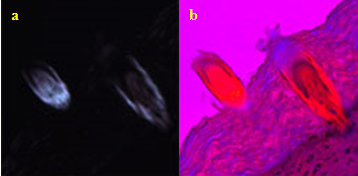
The first order retardation plate is frequently utilized to determine the optical sign of a birefringent specimen in polarized light microscopy. The optical sign includes positive and negative. If the ordinary wavefront is faster than the extraordinary wavefront (see [link] ), the specimen displays positive birefringence. Conversly, a negative birefringence will be detected if the ordinary wavefront is slower than the extraordinary wavefront. In addition, the retardation plate is also useful for enhancing contrast in weakly birefringent specimens. [link] shows the effect of first order retardation plate on the contrast of birefringence. The birefringence is so weak that the morphology on the edge of the tissue is hard to image, [link] a. When a first order retardation plate is added, the structure of the cell become all apparent compared with the one without retardation plate, [link] b.
[link] shows the images of liquid crystal phases from different specimens. First order retardation plates are utilized in all of these images. Apparent contrasts are detected here in the image which corresponds to the existence of liquid crystal phase within the specimen.

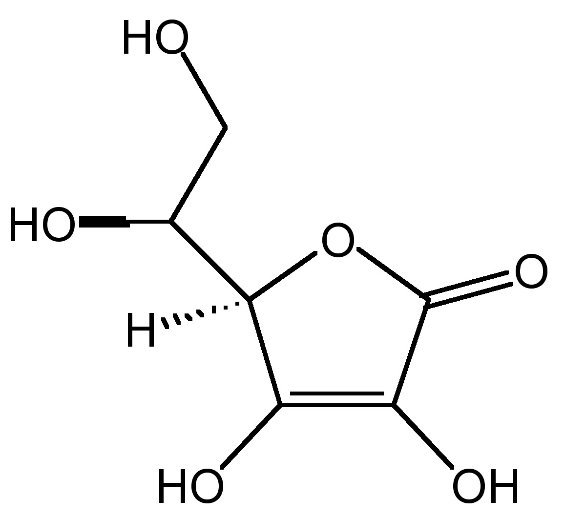
The effect of the angle between horizontal direction and polarizer transmission axis on the appearance of liquid crystal phase may be analyzed. In [link] is shown images of an ascorbic acid ( [link] ) sample under cross polar mode. When the polarizer rotates from 0° to 90°, big variations on the shape of bright domains and domain colors appear due to the change of wave vibrating directions. By rotating the polarizer, we can have a comprehensive understanding of the overall texture.


Notification Switch
Would you like to follow the 'Physical methods in chemistry and nano science' conversation and receive update notifications?