<< Chapter < Page Chapter >> Page >
(a) Dielectric probe (liquids are placed on this probe). Circuit schematic of impedance measurements for (b) low and (c) high impedance materials. Circuit symbols Osc, Zx, V, I, and R represent oscillator (i.e. frequency source), sample impedance, voltage, current, and resistance, respectively.

As can be seen in Figure 3, the RF I-V method, which incorporates the use of a dielectric probe, essentially measures variations in voltage and current when a sample is placed on the dielectric probe. For the low-impedance case, the impedance of the sample (Zx) is given by [link] , for a high-impedance sample, the impedance of the sample (Zx) is given by [link] .

Zx = V / I = 2R V 2 V 1 1 size 12{ ital "Zx"=V/I= { {2R} over { { {V rSub { size 8{2} } } over {V rSub { size 8{1} } } } - 1} } } {}
Zx = V / I = R 2 V 1 V 2 1 size 12{ ital "Zx"=V/I= { {R} over {2} } left [ { {V rSub { size 8{1} } } over {V rSub { size 8{2} } } } - 1 right ]} {}

The instrumentation and methods described herein consist of an Agilent E4991A impedance analyzer connected to an Agilent 85070E dielectric probe kit. The impedance analyzer directly measures the complex impedance of the sample under test by measuring either the frequency-dependent voltage or current across the sample. These values are then converted to permittivity values using the system software.

Applications

Electrical permittivity of deionized water and saline (0.9 % w/v nacl)

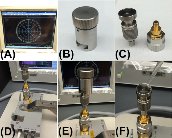
In order to acquire the electrical permittivity of aqueous solutions the impedance analyzer and dielectric probe must first be calibrated. In the first instance, the impedance analyzer unit is calibrated under open-circuit, short-circuit, 50 ohm load, and low loss capacitance conditions by attaching the relevant probes shown in [link] . The dielectric probe is then attached to the system and re-calibrated in open-air, with an attached short circuit probe, and finally with 500 μl of highly purified deionized water (with a resistivity of 18.2 MΩ/cm at 25 °C) ( [link] ). The water is then removed and the system is ready for acquiring data.
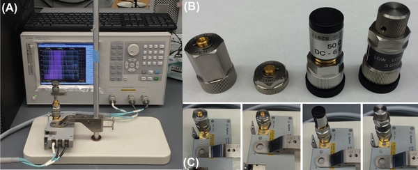
Impedance analyzer calibration (A) Agilent E4991A impedance analyzer connected to 85070E dielectric probe. (B) Calibrations standards (left-to-right: open circuit, short circuit, 50 ohm load, low-loss capacitor), (C) Attachment of the open circuit, short circuit, 50 ohm load, and low-loss capacitor (left-to-right, respectively).
Dielectric probe calibration. (A) Impedance analyzer screen shot showing data line for dielectric probe in open-air. (B) short circuit probe (C) dielectric probe (D) dielectric probe connected to impedance analyzer under open air conditions (E) short-circuit probe attached to dielectric probe (F) 500 μl of deionized water on dielectric probe.

In order to maintain accurate calibration only the purest deionized water with a resistivity of 18.2 MΩ/cm at 25 °C should be used. To perform an analysis simply load the dielectric probe with 500 μl of the sample and click on the ‘acquire data’ tab in the software. The system will perform a scan across the frequency range 200 MHz – 3 GHz and acquire the real and imaginary parts of the complex permittivity. The period with which a data point is taken as well as the scale (i.e. log or linear) can also be altered in the software if necessary. To analyze another sample, remove the liquid and gently dry the dielectric probe with a paper towel. An open air refresh calibration should then be performed (by pressing the relevant button in the software) as this prevents errors and instrument drift from sample to sample. To analyze a normal saline (0.9 % NaCl w/v) solution, dissolve 8.99 g of NaCl in 1 litre of DI water (18.2 MΩ/cm at 25 °C) to create a 154 mM NaCl solution (equivalent to a 0.9 % NaCl w/v solution). Load 500 μl of the sample on the dielectric probe and acquire a new data set as mentioned previously.

Users should consult the “ Agilent Installation and Quick Start Guide ” manual for full specifics in regards to impedance analyzer and dielectric probe calibration settings.

Data analysis

The data files extracted from the impedance analyzer and dielectric probe setup previously described can be opened using any standard data processing software such as Microsoft Excel. The data will appear in three columns, which will be labeled frequency (Hz), ε', and ε" (representing the real and imaginary components of the permittivity, respectively). Any graphing software can be used to create simple graphs of the complex permittivity versus frequency. In the example below ( [link] ) we have used Prism to graph the real and complex permittivity’s versus frequency (200 MHz – 3 GHz) for the water and saline samples. For this frequency range no error correction is needed. For the analysis of frequencies below 200 MHz down to 10 MHz, which can be achieved using the impedance analyzer and dielectric probe configuration, error correction algorithms are needed to take into account electrode polarization effects that skew and distort the data. Gach et al . cover these necessary algorithms that can be used if needed.
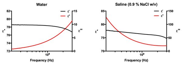
Real and Imaginary components of permittivity for water (left) and saline (right) samples across the frequency range 200 MHz – 3 GHz.

Bibliography

Questions & Answers

if three forces F1.f2 .f3 act at a point on a Cartesian plane in the daigram .....so if the question says write down the x and y components ..... I really don't understand
Syamthanda Reply
hey , can you please explain oxidation reaction & redox ?
Boitumelo Reply
hey , can you please explain oxidation reaction and redox ?
Boitumelo
for grade 12 or grade 11?
Sibulele
the value of V1 and V2
Tumelo Reply
advantages of electrons in a circuit
Rethabile Reply
we're do you find electromagnetism past papers
Ntombifuthi
what a normal force
Tholulwazi Reply
it is the force or component of the force that the surface exert on an object incontact with it and which acts perpendicular to the surface
Sihle
what is physics?
Petrus Reply
what is the half reaction of Potassium and chlorine
Anna Reply
how to calculate coefficient of static friction
Lisa Reply
how to calculate static friction
Lisa
How to calculate a current
Tumelo
how to calculate the magnitude of horizontal component of the applied force
Mogano
How to calculate force
Monambi
a structure of a thermocouple used to measure inner temperature
Anna Reply
a fixed gas of a mass is held at standard pressure temperature of 15 degrees Celsius .Calculate the temperature of the gas in Celsius if the pressure is changed to 2×10 to the power 4
Amahle Reply
How is energy being used in bonding?
Raymond Reply
what is acceleration
Syamthanda Reply
a rate of change in velocity of an object whith respect to time
Khuthadzo
how can we find the moment of torque of a circular object
Kidist
Acceleration is a rate of change in velocity.
Justice
t =r×f
Khuthadzo
how to calculate tension by substitution
Precious Reply
hi
Shongi
hi
Leago
use fnet method. how many obects are being calculated ?
Khuthadzo
khuthadzo hii
Hulisani
how to calculate acceleration and tension force
Lungile Reply
you use Fnet equals ma , newtoms second law formula
Masego
please help me with vectors in two dimensions
Mulaudzi Reply
how to calculate normal force
Mulaudzi
Got questions? Join the online conversation and get instant answers!
Jobilize.com Reply

Get Jobilize Job Search Mobile App in your pocket Now!

Get it on Google Play Download on the App Store Now


Source:  OpenStax, Physical methods in chemistry and nano science. OpenStax CNX. May 05, 2015 Download for free at http://legacy.cnx.org/content/col10699/1.21
Google Play and the Google Play logo are trademarks of Google Inc.

Notification Switch

Would you like to follow the 'Physical methods in chemistry and nano science' conversation and receive update notifications?

Ask