<< Chapter < Page Chapter >> Page >

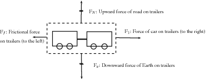
If we draw a box around the two trailers they can be considered a closed system or unit. When we look at the forces on this closed system the following forces will apply (we assume drag forces are absent):

  • The force of the car pulling the unit (trailer A and B)
  • The force of friction between the wheels of the trailers and the road (opposite to the direction of motion)
  • The force of the Earth pulling downwards on the system (gravity)
  • The force of the road pushing upwards on the system

These forces are called external forces to the system.

The following forces will not apply:

  • The force of A pulling B
  • The force of B pulling A
  • The force of friction between the wheels of the car and the road (opposite to the direction of motion)

We can also draw a box around trailer A or B, in which case the forces will be different.

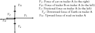
If we consider trailer A as a system, the following external forces will apply:

  • The force of the car pulling on A (towards the right)
  • The force of B pulling on A (towards the left)
  • The force of the Earth pulling downwards on the trailer (gravity)
  • The force of the road pushing upwards on the trailer
  • The force of friction between the wheels of A and the road (opposite to the direction of motion)

Force diagrams

If we look at the example above and draw a force diagram of all the forces acting on the two-trailer-unit, the diagram would look like this:
It is important to keep the following in mind when you draw force diagrams:

  • Make your drawing large and clear.
  • You must use arrows and the direction of the arrow will show the direction of the force.
  • The length of the arrow will indicate the size of the force, in other words, the longer arrows in the diagram (F 1 for example) indicates a bigger force than a shorter arrow (F f ). Arrows of the same length indicate forces of equal size (F N and F g ). Use “little lines” like in maths to show this.
  • Draw neat lines using a ruler. The arrows must touch the system or object.
  • All arrows must have labels. Use letters with a key on the side if you do not have enough space on your drawing.
  • The labels must indicate what is applying the force (the force of the car?) on what the force is applied (?on the trailer?) and in which direction (to the right)
  • If the values of the forces are known, these values can be added to the diagram or key.

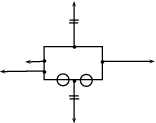
Draw a labeled force diagram to indicate all the forces acting on trailer A in the example above.

Got questions? Get instant answers now!

Free body diagrams

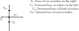
In a free-body diagram, the object of interest is drawn as a dot and all the forces acting on it are drawn as arrows pointing away from the dot. A free body diagram for the two-trailer-system will therefore look like this:

Draw a free body diagram of all the forces acting on trailer A in the example above.
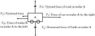
Got questions? Get instant answers now!

Finding the resultant force

The easiest way to determine a resultant force is to draw a free body diagram. Remember from Vectors that we use the length of the arrow to indicate the vector's magnitude and the direction of the arrow to show which direction it acts in.

Get Jobilize Job Search Mobile App in your pocket Now!

Get it on Google Play Download on the App Store Now


Source:  OpenStax, Siyavula textbooks: grade 11 physical science. OpenStax CNX. Jul 29, 2011 Download for free at http://cnx.org/content/col11241/1.2
Google Play and the Google Play logo are trademarks of Google Inc.

Notification Switch

Would you like to follow the 'Siyavula textbooks: grade 11 physical science' conversation and receive update notifications?

Ask