| << Chapter < Page | Chapter >> Page > |
Block on an incline
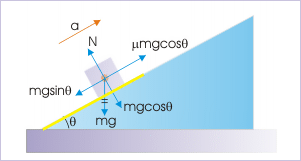
Note that friction has to be greater than the component of gravity along the incline as net component should be directed up to produce deceleration of the block. It means that had the block started motion on the plane in this section, it would not have moved down without external aid. Substituting for acceleration from consideration in upper half, we have :
Problem 3 : Two blocks “A” and “B” of mass 4 kg and 8 kg respectively are placed side by side on a rough incline of angle 30°. The blocks are released to slide down the incline at the same instant. The coefficients of friction for block “A” and “B” with the incline are 0.2 and 0.3 respectively. Find the accelerations of the blocks.
Two blocks on an incline
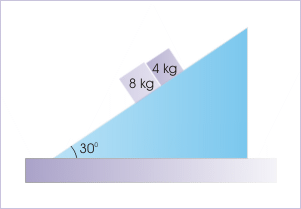
Solution : The incline surface is rough. We need to check relative accelerations of the two blocks to know whether they travel together or separately. The blocks are under the same component of acceleration due to gravity along the incline.
The deceleration due to friction for two blocks are :
Clearly, the deceleration due to friction for block “A” is less than that for block “B”. This means that block “A” will always press against block “B”.
Two blocks on an incline
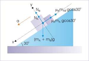
Thus, two blocks will move together. Let “a” be the common acceleration. We can analyze the motion treating two blocks as one, having mass of 12 kg. The free body diagram of the combined block is superimposed on the figure. Note that we have combined weight, but not the friction as it is different as coefficients of friction are different for two blocks.
Problem 4 : Two blocks “A” and “B” have mass 2 kg and 4 kg respectively slide down an incline of angle 45°. They are connected through a “mass-less” rod as shown in the figure. The coefficients of friction between surface and blocks “A” and “B” are 0.75 and 0.25 respectively. Find the tension in the connecting rod.
Two blocks on an incline
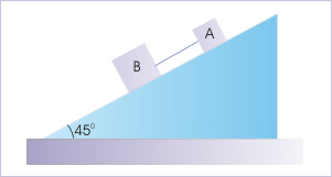
Solution : According to question, the blocks along with connecting rod slides down the incline. Since connecting rod is inflexible, the motion of two blocks is constrained. They move together with a common acceleration. Let the common acceleration be “a”. In the figure below, we have drawn forces considering combined mass in direction parallel to incline. Note that we have not drawn forces perpendicular to incline to keep the diagram simple. From the analysis of force along the incline, we have :
Two blocks on an incline
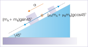
In order to find tension in the rod, we consider the free body diagram of block “A”.
Free body diagram
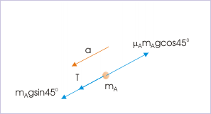
Since value of “T” is positive, the assumed direction of tension in the free body diagram is correct.
Author wishes to acknowledge Mr Lim Swee Sien for pointing out a mistake in the module.

Notification Switch
Would you like to follow the 'Physics for k-12' conversation and receive update notifications?