| << Chapter < Page | Chapter >> Page > |
By the end of this section, you will be able to:
The information presented in this section supports the following AP® learning objectives and science practices:
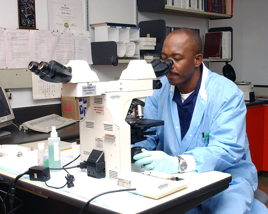
Although the eye is marvelous in its ability to see objects large and small, it obviously has limitations to the smallest details it can detect. Human desire to see beyond what is possible with the naked eye led to the use of optical instruments. In this section we will examine microscopes, instruments for enlarging the detail that we cannot see with the unaided eye. The microscope is a multiple-element system having more than a single lens or mirror. (See [link] ) A microscope can be made from two convex lenses. The image formed by the first element becomes the object for the second element. The second element forms its own image, which is the object for the third element, and so on. Ray tracing helps to visualize the image formed. If the device is composed of thin lenses and mirrors that obey the thin lens equations, then it is not difficult to describe their behavior numerically.

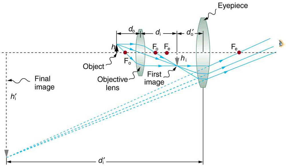
Microscopes were first developed in the early 1600s by eyeglass makers in The Netherlands and Denmark. The simplest compound microscope is constructed from two convex lenses as shown schematically in [link] . The first lens is called the objective lens , and has typical magnification values from to . In standard microscopes, the objectives are mounted such that when you switch between objectives, the sample remains in focus. Objectives arranged in this way are described as parfocal. The second, the eyepiece , also referred to as the ocular, has several lenses which slide inside a cylindrical barrel. The focusing ability is provided by the movement of both the objective lens and the eyepiece. The purpose of a microscope is to magnify small objects, and both lenses contribute to the final magnification. Additionally, the final enlarged image is produced in a location far enough from the observer to be easily viewed, since the eye cannot focus on objects or images that are too close.

To see how the microscope in [link] forms an image, we consider its two lenses in succession. The object is slightly farther away from the objective lens than its focal length , producing a case 1 image that is larger than the object. This first image is the object for the second lens, or eyepiece. The eyepiece is intentionally located so it can further magnify the image. The eyepiece is placed so that the first image is closer to it than its focal length . Thus the eyepiece acts as a magnifying glass, and the final image is made even larger. The final image remains inverted, but it is farther from the observer, making it easy to view (the eye is most relaxed when viewing distant objects and normally cannot focus closer than 25 cm). Since each lens produces a magnification that multiplies the height of the image, it is apparent that the overall magnification is the product of the individual magnifications:

Notification Switch
Would you like to follow the 'College physics for ap® courses' conversation and receive update notifications?