| << Chapter < Page | Chapter >> Page > |
SSPD_Chapter 6_Part 7_Introduction to ATHENA2
SECTION 7.7 Background of ATHENAcontinued.
7.7.2. Creating Device Structure using ATHENA

7.7.2.6. Reducing Grid Points in Non-Essential Areas using the Relax Parameter
The previous sections demonstrate that the quality of the grid is extremely important for ATHENA simulation. The rectangular based grid generated by the INITIALIZE or DEPOSIT statements may remain intact in those areas not involved in the process steps affecting the grid (e.g., etching or oxidation). The Grid Relax capability allows the spacing to be increased in such areas at any point which are not critical in the process step during the simulation. This capability is useful for two reasons. First, the initial small spacings are propagated throughout the structure. For example, the fine grid in the X-direction shown in Figure 7.23 may be needed only in the upper portion of the structure where doping occurs. Eliminating some grid lines and points in the lower portion of the structure will not affect the accuracy of implant and diffusion simulation. Second, it is always necessary to set a fine grid in the area where ion implantation takes place, but the fine grid may be unnecessary after the profile is levelled-off during thermal steps. So, relaxation of an initially fine grid may save simulation time during subsequent steps. Parameters for the RELAX statement are set from the ATHENA Relax Menu.
To open this menu, select Structure → Relax... in the DECKBUILD Commands menu. You can preform grid relaxation over the whole structure if you select Entire Grid, or within a selected rectangular area, if you choose Selected and specify Xmin, Xmax, Ymin, and Ymax in Location Select. Selecting a material from the Material menu specifies which material region will be affected by the grid relax operation. The default is all materials within the specified area. You can perform the grid line elimination either in one direction or in both directions by selecting X direction, Y direction, or Both. The X direction, Relax, cannot be performed for individual materials except for the substrate.
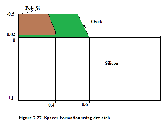
To understand how the relax function changes a grid, we will use the structure we have obtained after spacer formation was specified . If we relax the entire grid in both directions , the following lines will be inserted into the tutorial input file:
# RELAX EVERYWHERE RELAX DIR.X=T DIR.Y=T
Here ‘T’ is True and ‘F’ is False.
The total number of grid points is reduced from 708 to 388. When comparing with the grid before relaxation, note that the grid within the oxide spacer and polygate has not changed. This is due to three factors:
• the relax algorithm works only with rectangular base grid,
• it never eliminates grid lines adjacent to a region boundary,
• the relaxed area should be at least five by five grid points.
Within silicon, each second horizontal line is eliminated. The lower part of each second vertical line is also eliminated. This happens because the algorithm doesn’t allow the formation of obtuse triangles.
If you don’t want the grid to be relaxed above y=0.3, choose Selected and set all four boundaries in the Relax box. This will give the following RELAX statement:
# RELAX LOWER HALF OF THE STRUCTURE
RELAX X.MIN=0.00 X.MAX=1.00 Y.MIN=0.3 Y.MAX=1.00 DIR.X=T DIR.Y=T
In this case, the number of grid points is 567. The grid above y=0.3 remains intact and the elimination in X and Y- directions happens only below y=0.3.
To increase spacing only in the X-direction in the area below y=0.3, select the X direction and leave the Area and Location Selections as before. This will give the following Relax statement:
# RELAX LOWER HALF ONLY IN X-DIRECTION
RELAX X.MIN=0.00 X.MAX=1.00 Y.MIN=0.3 Y.MAX=1.00 DIR.X=T DIR.Y=F
Note: The only difference is that instead of DIR.Y=T, the statement contains DIR.Y=F, which prevents elimination in Y- direction. This gives 638 grid points and a different pattern of elimination
You can also apply several consequent RELAX statements to achieve grid elimination in different areas of the structure.
An important thing to remember about the RELAX capability is that it allows you to avoid creating obtuse triangles and avoid relaxing directly on the material boundaries. This sometimes results in no relaxation or grid relaxation in a subset of the desired area. The most desirable method for complete control over gridding is by using DEVEDIT as described briefly in this chapter and in the VWF INTERACTIVE TOOLS User’s Manual, Vol. II.

Notification Switch
Would you like to follow the 'Solid state physics and devices-the harbinger of third wave of civilization' conversation and receive update notifications?