| << Chapter < Page | Chapter >> Page > |

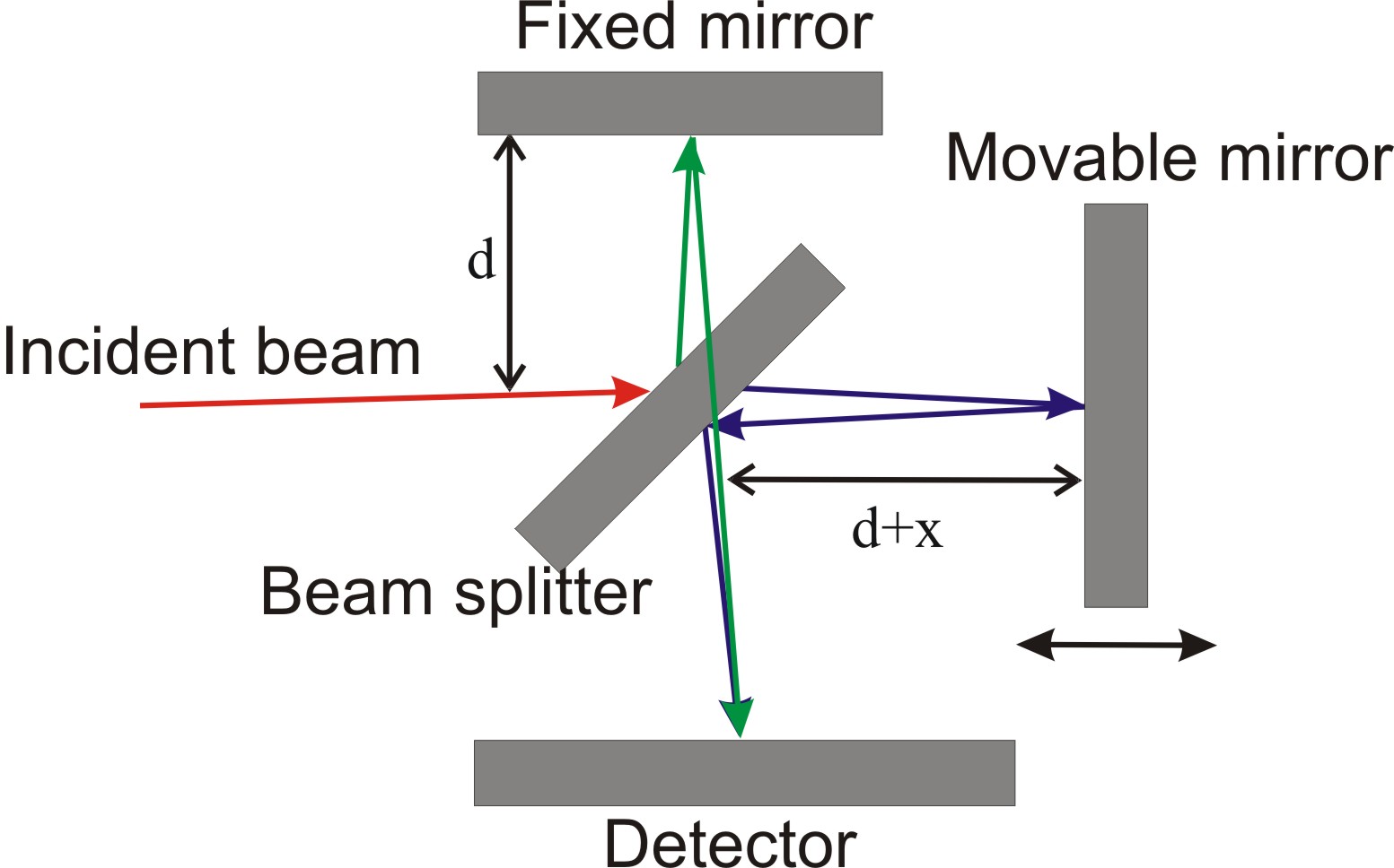
The difference of path lengths between two beams is 2x because beams traverse the designated distances twice. The interference occurs when the path difference is equal to integer numbers of wavelengths,
Modern interferometric systems are more complicated. Using special phase-measurement techniques they capable to perform much more accurate height measurements than can be obtained just by directly looking at the interference fringes and measuring how they depart from being straight and equally spaced. Typically interferometric system consist of lights source, beamsplitter, objective system, system of registration of signals and transformation into digital format and computer which process data. Vertical scanning interferometry is contains all these parts. [link] shows a configuration of VSI interferometric system.

Many of modern interferometric systems use Mirau objective in their constructions. Mireau objective is based on a Michelson interferometer. This objective consists of a lens, a reference mirror and a beamsplitter. The idea of getting interfering beams is simple: two beams (red lines) travel along the optical axis. Then they are reflected from the reference surface and the sample surface respectively (blue lines). After this these beams are recombined to interfere with each other. An illumination or light source system is used to direct light onto a sample surface through a cube beam splitter and the Mireau objective. The sample surface within the field of view of the objective is uniformly illuminated by those beams with different incidence angles. Any point on the sample surface can reflect those incident beams in the form of divergent cone. Similarly, the point on the reference symmetrical with that on the sample surface also reflects those illuminated beams in the same form.
The Mireau objective directs the beams reflected of the reference and the sample surface onto a CCD (charge-coupled device) sensor through a tube lens. The CCD sensor is an analog shift register that enables the transportation of analog signals (electric charges) through successive stages (capacitors), controlled by a clock signal. The resulting interference fringe pattern is detected by CCD sensor and the corresponding signal is digitized by a frame grabber for further processing with a computer.
The distance between a minimum and a maximum of the interferogram produced by two beams reflected from the reference and sample surface is known. That is, exactly half the wavelength of the light source. Therefore, with a simple interferogram the vertical resolution of the technique would be also limited to λ/2. If we will use a laser light as a light source with a wavelength of 300 nm the resolution would be only 150 nm. This resolution is not good enough for a detailed near-atomic scale investigation of crystal surfaces. Fortunately, the vertical resolution of the technique can be improved significantly by moving either the reference or the sample by a fraction of the wavelength of the light. In this way, several interferograms are produced. Then they are all overlayed, and their phase shifts compared by the computer software [link] . This method is widely known as phase shift interferometry (PSI).

Notification Switch
Would you like to follow the 'Chemistry of electronic materials' conversation and receive update notifications?