<< Chapter < Page Chapter >> Page >

In addition to the lowpass frequency response, other basic ideal responses are often needed in practice. The ideal highpass filterrejects signals with frequencies below a certain value and passes those with frequencies above that value. The ideal bandpass filter passes only aband of frequencies, and the ideal band reject filter completely rejects a band of frequencies. These ideal frequency responses are illustrated in [link] .
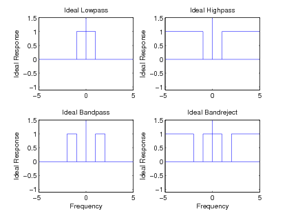
Figure one contains four cartesian graphs. Each graph's horizontal axis ranges in value from -5 to 5 in increments of 5, and their vertical axes are labeled Ideal response, ranging in value from -1 to 1.5 in increments of 0.5. The first graph, labeled Ideal lowpass, contains a horizontal line from (-5, 0) to (5, 0) and a vertical line from (0, 0) to (0, 1.5). The graph also contains line segments from approximately (-1, 0) to (-1, 1), (1, 0) to (1, 1) and (-1, 1) to (1, 1). The second graph, labeled Ideal highpass, contains a horizontal line from (-5, 0) to (5, 0) and a vertical line from (0, 0) to (0, 1.5). The graph also contains line segments from approximately (-5, 1) to (-1, 1), (-1, 1) to (-1, 0) (1, 0) to (1, 1), and (1, 1) to (5, 1). The third graph, labeled ideal bandpass, contains a horizontal line from (-5, 0) to (5, 0) and a vertical line from (0, 0) to (0, 1.5). The graph also contains line segments from approximately (-2, 0) to (-2, 1), (-2, 1) to (-1, 1), (-1, 1) to (-1, 0), (1, 0) to (1, 1), (1, 1) to (2, 1) and (2, 1) to (2, 0). The fourth graph, labeled ideal bandreject, contains a horizontal line from (-5, 0) to (5, 0) and a vertical line from (0, 0) to (0, 1.5). The graph also contains line segments from approximately (-5, 1) to (-2, 1), (-2, 1) to (-2, 0), (-1, 0) to (-1, 1), (1, 0) to (1, 1), (-1, 1) to (1, 1), (2, 0) to (2, 1), and (2, 1) to (5, 1).
The Basic Four Ideal Frequency Responses

This section presents a method for designing the three new filters by using a frequency transformation on the basic lowpass design. When used onthe four classical IIR approximations (e.g. Butterworth, Chebyshev, inverse-Chebyshev, and Elliptic Function), the optimality is preserved.This procedure is used in the FREQXFM() subroutine of Program 8 in the appendix.

Change the bandedge

The classical filters have all been developed for a bandedge of ω 0 = 1 . That is where the Butterworth filter has a magnitude squared of one half: | F | = 0 . 5 or the Chebyshev filter has its passband edge or the Inverse Chebyshev has its stopband edge or the Elliptic filterhas its passband edge. To scale the bandedge, simply replace s by K s or: s K s where K is reciprocal of the new desired bandedge. What happened to the prototype filter at ω = 1 will now happen at ω = 1 / K . It is simply a linear scaling of the ω axis. This change can be done before the conversions below or after.

The highpass filter

The frequency response illustrated in [link] b can be obtained from that in [link] a by replacing the complex frequency variable s in the transfer function by 1 / s . This change of variable maps zero frequency to infinity, maps unity into unity, andmaps infinity to zero. It turns the complex s plane inside out and leaves the unit circle alone.

In the design procedure, the desired bandedge ω 0 for the highpass filter is mapped by 1 / ω 0 to give the bandedge for the prototype lowpass filter. This lowpass filter is next designed byone of the optimal procedures already covered and then converted to a highpass transfer function by replacing s by 1 / s . If an elliptic-function filter approximation is used, both the passbandedge ω p and the stopbandedge ω s are transformed. Because most optimal lowpass design procedures give the designed transferfunction in factored form from explicit formulas for the poles and zeros, the transformation can be performed on each pole andzero to give the highpass transfer function in factored form.

The bandpass filter

In order to convert the lowpass filter of [link] a into that of [link] c, a more complicated frequency transformation is required. In order to reduce confusion, the complexfrequency variable for the prototype analog filter transfer function will be denoted by p and that for the transformed analog filter by s . The transformation is given by

p = s 2 + ω 0 2 s

This change of variables doubles the order of the filter, maps the origin of the s -plane to both plus and minus j ω 0 , and maps minus and plus infinity to zero and infinity. The entire ω axis of the prototype response is mapped between zero and plus infinity on thetransformed responses. It is also mapped onto the left-half axis between minus infinity and zero. This is illustrated in [link] .

Questions & Answers

if three forces F1.f2 .f3 act at a point on a Cartesian plane in the daigram .....so if the question says write down the x and y components ..... I really don't understand
Syamthanda Reply
hey , can you please explain oxidation reaction & redox ?
Boitumelo Reply
hey , can you please explain oxidation reaction and redox ?
Boitumelo
for grade 12 or grade 11?
Sibulele
the value of V1 and V2
Tumelo Reply
advantages of electrons in a circuit
Rethabile Reply
we're do you find electromagnetism past papers
Ntombifuthi
what a normal force
Tholulwazi Reply
it is the force or component of the force that the surface exert on an object incontact with it and which acts perpendicular to the surface
Sihle
what is physics?
Petrus Reply
what is the half reaction of Potassium and chlorine
Anna Reply
how to calculate coefficient of static friction
Lisa Reply
how to calculate static friction
Lisa
How to calculate a current
Tumelo
how to calculate the magnitude of horizontal component of the applied force
Mogano
How to calculate force
Monambi
a structure of a thermocouple used to measure inner temperature
Anna Reply
a fixed gas of a mass is held at standard pressure temperature of 15 degrees Celsius .Calculate the temperature of the gas in Celsius if the pressure is changed to 2×10 to the power 4
Amahle Reply
How is energy being used in bonding?
Raymond Reply
what is acceleration
Syamthanda Reply
a rate of change in velocity of an object whith respect to time
Khuthadzo
how can we find the moment of torque of a circular object
Kidist
Acceleration is a rate of change in velocity.
Justice
t =r×f
Khuthadzo
how to calculate tension by substitution
Precious Reply
hi
Shongi
hi
Leago
use fnet method. how many obects are being calculated ?
Khuthadzo
khuthadzo hii
Hulisani
how to calculate acceleration and tension force
Lungile Reply
you use Fnet equals ma , newtoms second law formula
Masego
please help me with vectors in two dimensions
Mulaudzi Reply
how to calculate normal force
Mulaudzi
Got questions? Join the online conversation and get instant answers!
Jobilize.com Reply

Get Jobilize Job Search Mobile App in your pocket Now!

Get it on Google Play Download on the App Store Now


Source:  OpenStax, Digital signal processing and digital filter design (draft). OpenStax CNX. Nov 17, 2012 Download for free at http://cnx.org/content/col10598/1.6
Google Play and the Google Play logo are trademarks of Google Inc.

Notification Switch

Would you like to follow the 'Digital signal processing and digital filter design (draft)' conversation and receive update notifications?

Ask