<< Chapter < Page Chapter >> Page >
  • Describe the effects of the magnetic force between two conductors.
  • Calculate the force between two parallel conductors.

You might expect that there are significant forces between current-carrying wires, since ordinary currents produce significant magnetic fields and these fields exert significant forces on ordinary currents. But you might not expect that the force between wires is used to define the ampere. It might also surprise you to learn that this force has something to do with why large circuit breakers burn up when they attempt to interrupt large currents.

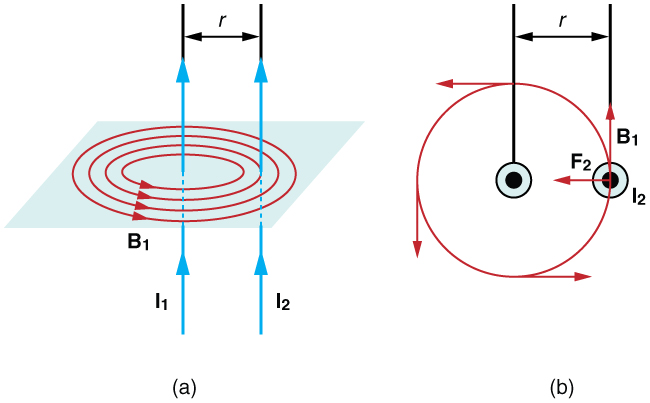
The force between two long straight and parallel conductors separated by a distance r size 12{r} {} can be found by applying what we have developed in preceding sections. [link] shows the wires, their currents, the fields they create, and the subsequent forces they exert on one another. Let us consider the field produced by wire 1 and the force it exerts on wire 2 (call the force F 2 size 12{F rSub { size 8{2} } } {} ). The field due to I 1 size 12{I rSub { size 8{1} } } {} at a distance r size 12{r} {} is given to be

B 1 = μ 0 I 1 2 πr . size 12{B rSub { size 8{1} } = { {μ rSub { size 8{0} } I rSub { size 8{1} } } over {2πr} } "." } {}
Figure a shows two parallel wires, both with currents going up. The magnetic field lines of the first wire are shown as concentric circles centered on wire 1 and in a plane perpendicular to the wires. The magnetic field is in the counter clockwise direction as viewed from above. Figure b shows a view from above and shows the current-carrying wires as two dots. Around wire one is a circle that represents a magnetic field line due to that wire. The magnetic field passes directly through wire two. The magnetic field is in the counter clockwise direction. The force on wire two is to the left, toward wire one.
(a) The magnetic field produced by a long straight conductor is perpendicular to a parallel conductor, as indicated by RHR-2. (b) A view from above of the two wires shown in (a), with one magnetic field line shown for each wire. RHR-1 shows that the force between the parallel conductors is attractive when the currents are in the same direction. A similar analysis shows that the force is repulsive between currents in opposite directions.

This field is uniform along wire 2 and perpendicular to it, and so the force F 2 size 12{F rSub { size 8{2} } } {} it exerts on wire 2 is given by F = IlB sin θ size 12{F= ital "IlB""sin"θ} {} with sin θ = 1 size 12{"sin"θ=1} {} :

F 2 = I 2 lB 1 . size 12{F rSub { size 8{2} } =I rSub { size 8{2} } ital "lB" rSub { size 8{1} } } {}

By Newton’s third law, the forces on the wires are equal in magnitude, and so we just write F size 12{F} {} for the magnitude of F 2 size 12{F rSub { size 8{2} } } {} . (Note that F 1 = F 2 size 12{F rSub { size 8{1} } = - F rSub { size 8{2} } } {} .) Since the wires are very long, it is convenient to think in terms of F / l size 12{F/l} {} , the force per unit length. Substituting the expression for B 1 size 12{B rSub { size 8{1} } } {} into the last equation and rearranging terms gives

F l = μ 0 I 1 I 2 2 πr . size 12{ { {F} over {l} } = { {μ rSub { size 8{0} } I rSub { size 8{1} } I rSub { size 8{2} } } over {2πr} } "." } {}

F / l size 12{F/l} {} is the force per unit length between two parallel currents I 1 size 12{I rSub { size 8{1} } } {} and I 2 size 12{I rSub { size 8{2} } } {} separated by a distance r size 12{r} {} . The force is attractive if the currents are in the same direction and repulsive if they are in opposite directions.

This force is responsible for the pinch effect in electric arcs and plasmas. The force exists whether the currents are in wires or not. In an electric arc, where currents are moving parallel to one another, there is an attraction that squeezes currents into a smaller tube. In large circuit breakers, like those used in neighborhood power distribution systems, the pinch effect can concentrate an arc between plates of a switch trying to break a large current, burn holes, and even ignite the equipment. Another example of the pinch effect is found in the solar plasma, where jets of ionized material, such as solar flares, are shaped by magnetic forces.

The operational definition of the ampere is based on the force between current-carrying wires. Note that for parallel wires separated by 1 meter with each carrying 1 ampere, the force per meter is

F l = × 10 7 T m/A 1 A 2 2 π 1 m = 2 × 10 7 N/m. size 12{ { {F} over {l} } = { { left (4π times "10" rSup { size 8{ - 7} } `T cdot "m/A" right ) left (1`A right ) rSup { size 8{2} } } over { left (2π right ) left (1" m" right )} } =2 times "10" rSup { size 8{ - 7} } " N/m" "." } {}

Get Jobilize Job Search Mobile App in your pocket Now!

Get it on Google Play Download on the App Store Now


Source:  OpenStax, Basic physics for medical imaging. OpenStax CNX. Feb 17, 2014 Download for free at http://legacy.cnx.org/content/col11630/1.1
Google Play and the Google Play logo are trademarks of Google Inc.

Notification Switch

Would you like to follow the 'Basic physics for medical imaging' conversation and receive update notifications?

Ask