| << Chapter < Page | Chapter >> Page > |
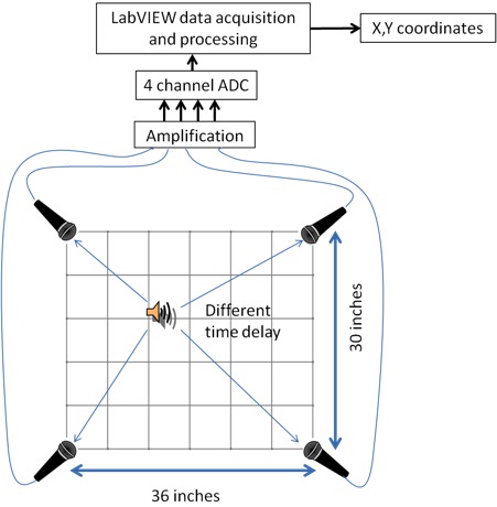
Our system is made up of 4 monochannel mics, a breadboard with 4 amplifiers (OP741), a 4 channel Analog to Digital converter (ADC, NI 9234) connected via a chasis (NI cDAQ-9174) to the computer through USB connectors. The overview of our system is shown in the figure below. Gathering of data from ADC is done through the LabVIEW program, and calculation of the x and y coordinates via the microphone delays is also done inside the program.
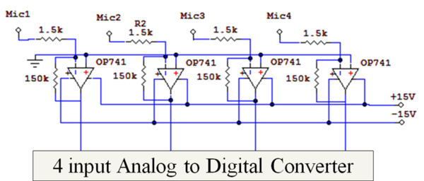
Since the microphones are monochannel, their sound transduced voltage data is output through a single 3.5mm audio jack. The amplifier circuit is done using OP741 with the circuit shown below, with a gain of -100X per channel. Gain is calculated through the following equation

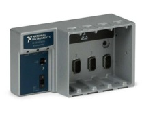
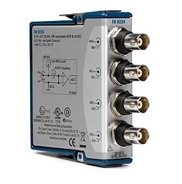
The Analog to Digital convertor (ADC) system is obtained from National Instrument. The input module is NI 9234 while the USB chasis is NI cDAQ-9174. The ADC is capable of obtaining up to 51.2kSamples/sec, which will allow us to process up to 39.0625μs of time difference accurately.
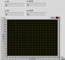
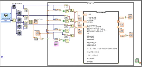
The labview interface is built using the system blocks shown below. Data is collected in chunks of 12.8k samples which correspond to 0.5seconds of acquisition per calculation. Using those data, we set a threshold value, which will trigger LabVIEW to output a the time at which the threshold is crossed. As each microphone picks up the sound at a different time, the time at which their voltage crosses the threshold is different. Using this delay, we are able calculate the x and y coordinate which will be output to a point in a graph.

Notification Switch
Would you like to follow the 'Sound positioning system' conversation and receive update notifications?