| << Chapter < Page | Chapter >> Page > |
Notice that the reconstructed signal is scaled by the factor .
Of course, the sample-and-hold does not generate perfect impulses. Instead it generates a pulseof width , and magnitude equal to the input sample. Therefore, the new signal out of the sample-and-holdis equivalent to the old signal (an impulse train) convolved with the pulse
Convolution in the time domain is equivalent to multiplication in the frequency domain,so this convolution with is equivalent to multiplying by the Fourier transform where
Finally, the magnitude of the frequency response of the -th order Butterworth filter is given by
We may calculate the complete magnitude response of the sample-and-hold system by combining the effects of the Butterworth filters in [link] , the ideal sampling system in [link] , and the sample-and-hold pulse width in [link] . This yields the final expression
Notice that the expression produces a roll-off in frequency which will attenuate frequencies close to the Nyquistrate. Generally, this roll-off is not desirable.
f = -1:.001:1 .

In this lab we will use Simulink to simulate the effects of the sampling and reconstruction processes.Simulink treats all signals as continuous-time signals. This means that “sampled” signals are really just continuous-time signals that contain a series offinite-width pulses. The height of each of these pulses is the amplitude of the input signal at the beginning of the pulse. In other words, boththe sampling action and the zero-order-hold reconstruction are done at the same time; the discrete-time signal itself is never generated.This means that the impulse-generator block is really a “pulse-generator”, or zero-order-hold device. Remember that, in Simulink,frequency spectra are computed on continuous-time signals. This is why many aliasedcomponents will appear in the spectra.
For help on the following topics select the corresponding links: simulink and printing figures in simulink . For the following section, download the file Lab4Utils.zip .
In this section, we will experiment with the sampling and reconstruction of signals using a pulse generator.This pulse generator is the combination of an ideal impulse generator and a perfect zero-order-hold device.
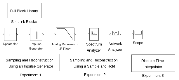
In order to run the experiment, first download the required Lab4Utilities . Once Matlab is started, type “Lab4”.A set of Simulink blocks and experiments will come up as shown in [link] .

Notification Switch
Would you like to follow the 'Purdue digital signal processing labs (ece 438)' conversation and receive update notifications?