| << Chapter < Page | Chapter >> Page > |
In AM transmission where the baseband signal and its modulated passband version are real valued,the spectrum of the modulated signal has twice the bandwidth of the baseband signal.As pictured in [link] , the spectrum of the baseband signal is nonzero only forfrequencies between and . After modulation, the spectrum is nonzero in the interval and in the interval . Thus the total width of frequencies occupied by the modulated signal is twicethat occupied by the baseband signal. This represents a kind of inefficiency or redundancyin the transmission. Quadrature modulation provides one way of removing this redundancyby sending two messages in the frequency ranges between and , thus utilizing the spectrum more efficiently.
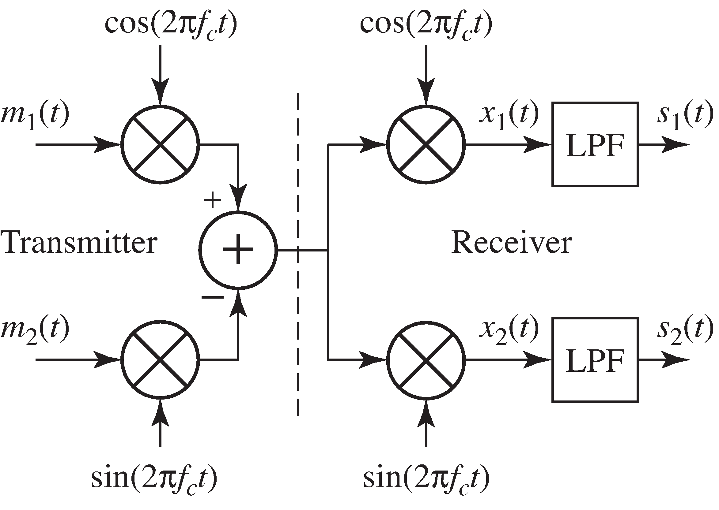
To see how this can work, suppose that there are two message streams and . Modulate one message with a cosine to create the in-phase signal, and the other with (the negative of) a sine to form the quadrature signal. These are summed These are also sometimes modeled as the “real” and the “imaginary”parts of a single “complex valued” signal. This complex representation is explored more fully inAppendix [link] . to form
which is then transmitted. A receiver structure that can recover the two messagesis shown in [link] . The signal at the output of the receiver is intended to recover the first message . Similarly, the signal at the output of the receiver is intended to recover the (negative of the) second message .
To examine the recovered signals and in [link] , first evaluate the signals before the lowpass filtering. Using the trigonometric identities [link] and [link] , becomes

Lowpass filtering produces
Similarly, can be rewritten using [link] and [link]
and lowpass filtering produces
Thus, in the ideal situation in which the phases and frequencies of the modulation and the demodulation are identical, bothmessages can be recovered. But if the frequencies and/orphases are not exact, then problems analogous to those encountered with AM will occur in the quadrature modulation.For instance, if the phase of (say) the demodulator is not correct, then there will be some distortion or attenuation in . However, problems in the demodulation of may also cause problems in the demodulation of . This is called cross-interference between the two messages.
Use
AM.m as a starting point to create a quadrature
modulation system that implements the block diagram of
[link] .

Notification Switch
Would you like to follow the 'Software receiver design' conversation and receive update notifications?