| << Chapter < Page | Chapter >> Page > |

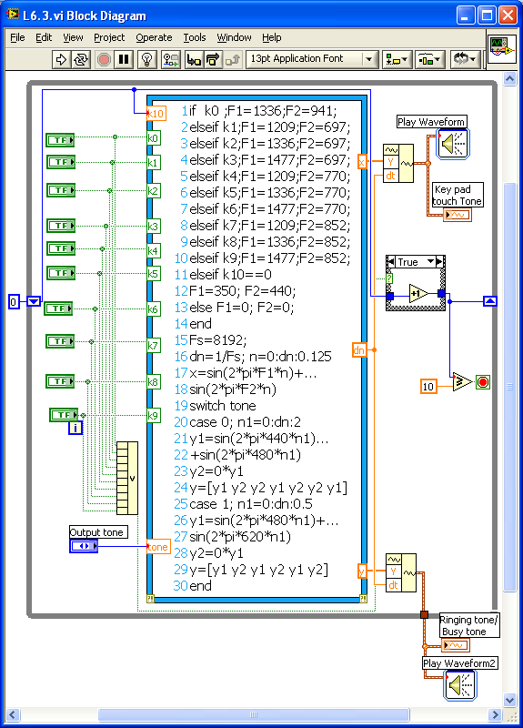
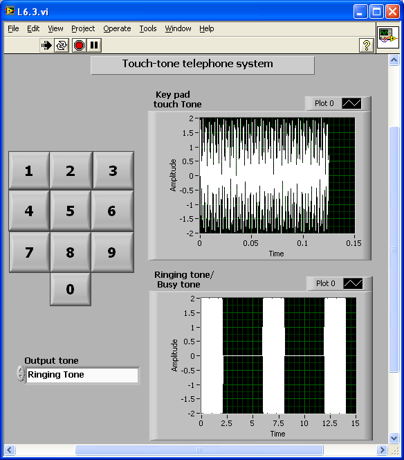
[link] shows the front panel of the touch-tone telephone system. When the program is run, one can hear the dial tone and see the signal displayed in the upper waveform graph. As soon as any number key is pressed, the dial tone is stopped and the corresponding key pad tone is heard and displayed. When keys are pressed 10 times (a valid phone number), the system plays the ringing tone or busy tone depending on the setting and displays the tone in the lower waveform graph.

Dithering
Dithering is a method of decreasing the distortion of a low-frequency signal due to signal digitization [link] . Dithering works best when the sample rate is high in comparison with the rate at which the signal changes.
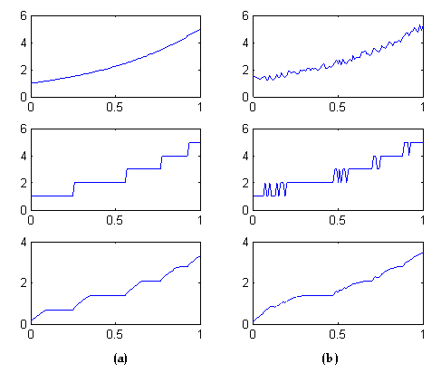
To see how this works, consider a slowly varying signal and its digitization, shown in [link] (a). If noise is added to the original signal amplitude roughly at one half the step size, the signal will look like [link] (b). If the digitized signal is passed through a resistor-capacitor circuit to smooth it out, an approximation to the original signal can be recovered. There is no theoretical limit to the accuracy possible with this method as long as the sampling rate is high enough.
Design a system to analyze the dithering technique. First, show the digitized and smoothed signal without dithering. Then, add random noise to the input signal (noise level should not exceed 50 percent of the step size of the digitized signal) and show the digitized and smoothed version. Measure the maximum and average error between the original signal and recovered signal.

Insert Solution Text Here
Image Processing
DFT is widely used in image processing for edge detection. A digital image is a two-dimensional signal that can get stored and processed as a two-dimensional (2D) array. In the frequency domain, with the center denoting (0,0) frequency, the center portion of this 2D array contains the low-frequency components of the 2D signal or image. The edges in the image can be extracted by removing the low-frequency components.
Read and display the image file
fft2 and
fftshift .ifft2 and
fftshift . The processed image should reflect the edges in the original image.Insert Solution Text Here
DTMF Decoder
Design a decoder VI for the DTMF system described in Telephone Signal section. The VI should be capable of reading the touchtone signal as its input and display the corresponding decoded key number as its output.
Insert Solution Text Here

Notification Switch
Would you like to follow the 'An interactive approach to signals and systems laboratory' conversation and receive update notifications?