| << Chapter < Page | Chapter >> Page > |
An electric circuit is a closed path (with no breaks or gaps) along which electrical charges (electrons) flow powered by an energy source.
Some common elements (components) which can be found in electrical circuits include light bulbs, batteries, connecting leads, switches, resistors, voltmeters and ammeters. You will learn more about these items in later sections, but it is important to know what their symbols are and how to represent them in circuit diagrams. Below is a table with the items and their symbols:
| Component | Symbol | Usage |
| light bulb |
|
glows when charge moves through it |
| battery |
|
provides energy for charge to move - conventional current flow from positive to negative through a circuit |
| switch |
|
allows a circuit to be open or closed |
| resistor |
|
resists the flow of charge |
| OR | ||
|
|
||
| voltmeter |
|
measures potential difference |
| ammeter |
|
measures current in a circuit |
| connecting lead |
|
connects circuit elements together |
A physical circuit is the electric circuit you create with real components.
A circuit diagram is a drawing which uses symbols to represent the different components in the physical circuit.
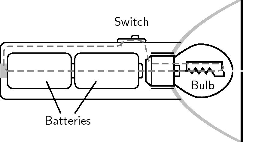
We use circuit diagrams to represent circuits because they are much simpler and more general than drawing the physical circuit because they only show the workings of the electrical components. You can see this in the two pictures below. The first picture shows the physical circuit for an electric torch. You can see the light bulb, the batteries, the switch and the outside plastic casing of the torch. The picture is actually a cross-section of the torch so that we can see inside it.

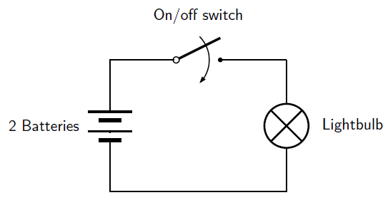
Below is the circuit diagram for the electric torch. Now the light bulb is represented by its symbol, as are the batteries, the switch and the connecting wires. It is not necessary to show the plastic casing of the torch since it has nothing to do with the electric workings of the torch. You can see that the circuit diagram is much simpler than the physical circuit drawing!

There are two ways to connect electrical components in a circuit: in series or in parallel .
In a series circuit, the charge flowing from the battery can only flow along a single path to return to the battery.
In a parallel circuit, the charge flowing from the battery can flow along multiple paths to return to the battery.
The picture below shows a circuit with two resistors connected in series on the left and a circuit with two resistors connected in parallel on the right. In the series circiut, the charge path from the battery goes through every component before returning to the battery. In the parallel circuit, there is more than one path for the charge to flow from the battery through one of the components and back to the battery.

Notification Switch
Would you like to follow the 'Physics - grade 10 [caps 2011]' conversation and receive update notifications?