| << Chapter < Page | Chapter >> Page > |
Although ac electric power is produced at relatively low voltages, it is sent through transmission lines at very high voltages (as high as 500 kV). The same power can be transmitted at different voltages because power is the product (For simplicity, we ignore the phase factor A particular power requirement can therefore be met with a low voltage and a high current or with a high voltage and a low current. The advantage of the high-voltage/low-current choice is that it results in lower ohmic losses in the transmission lines, which can be significant in lines that are many kilometers long ( [link] ).

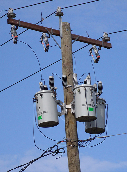
Typically, the alternating emfs produced at power plants are “stepped up” to very high voltages before being transmitted through power lines; then, they must be “stepped down” to relatively safe values (110 or 220 V rms) before they are introduced into homes. The device that transforms voltages from one value to another using induction is the transformer ( [link] ).

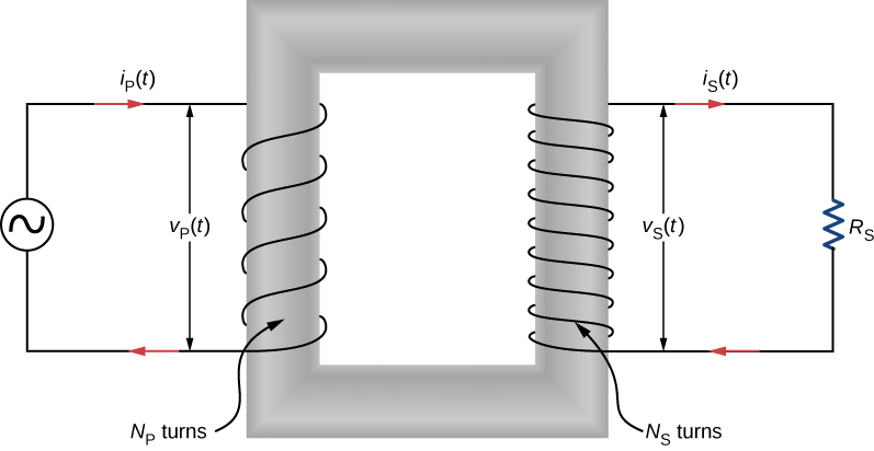
As [link] illustrates, a transformer basically consists of two separated coils, or windings, wrapped around a soft iron core. The primary winding has loops, or turns, and is connected to an alternating voltage The secondary winding has turns and is connected to a load resistor We assume the ideal case for which all magnetic field lines are confined to the core so that the same magnetic flux permeates each turn of both the primary and the secondary windings. We also neglect energy losses to magnetic hysteresis, to ohmic heating in the windings, and to ohmic heating of the induced eddy currents in the core. A good transformer can have losses as low as 1% of the transmitted power, so this is not a bad assumption.

To analyze the transformer circuit, we first consider the primary winding. The input voltage is equal to the potential difference induced across the primary winding. From Faraday’s law, the induced potential difference is where is the flux through one turn of the primary winding. Thus,
Similarly, the output voltage delivered to the load resistor must equal the potential difference induced across the secondary winding. Since the transformer is ideal, the flux through every turn of the secondary winding is also and

Notification Switch
Would you like to follow the 'University physics volume 2' conversation and receive update notifications?