| << Chapter < Page | Chapter >> Page > |
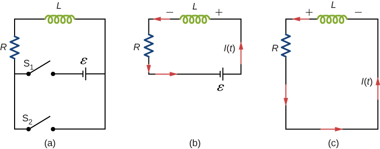
A circuit with resistance and self-inductance is known as an RL circuit. [link] (a) shows an RL circuit consisting of a resistor, an inductor, a constant source of emf, and switches and When is closed, the circuit is equivalent to a single-loop circuit consisting of a resistor and an inductor connected across a source of emf ( [link] (b)). When is opened and is closed, the circuit becomes a single-loop circuit with only a resistor and an inductor ( [link] (c)).

We first consider the RL circuit of [link] (b). Once is closed and is open, the source of emf produces a current in the circuit. If there were no self-inductance in the circuit, the current would rise immediately to a steady value of However, from Faraday’s law, the increasing current produces an emf across the inductor. In accordance with Lenz’s law, the induced emf counteracts the increase in the current and is directed as shown in the figure. As a result, I(t) starts at zero and increases asymptotically to its final value.
Applying Kirchhoff’s loop rule to this circuit, we obtain
which is a first-order differential equation for I(t) . Notice its similarity to the equation for a capacitor and resistor in series (See RC Circuits ). Similarly, the solution to [link] can be found by making substitutions in the equations relating the capacitor to the inductor. This gives
where
is the inductive time constant of the circuit.
The current I(t) is plotted in [link] (a). It starts at zero, and as , I(t) approaches asymptotically. The induced emf is directly proportional to dI / dt , or the slope of the curve. Hence, while at its greatest immediately after the switches are thrown, the induced emf decreases to zero with time as the current approaches its final value of The circuit then becomes equivalent to a resistor connected across a source of emf.

The energy stored in the magnetic field of an inductor is
Thus, as the current approaches the maximum current , the stored energy in the inductor increases from zero and asymptotically approaches a maximum of
The time constant tells us how rapidly the current increases to its final value. At the current in the circuit is, from [link] ,
which is of the final value . The smaller the inductive time constant the more rapidly the current approaches .
We can find the time dependence of the induced voltage across the inductor in this circuit by using and [link] :
The magnitude of this function is plotted in [link] (b). The greatest value of it occurs when dI/dt is greatest, which is immediately after is closed and is opened. In the approach to steady state, dI/dt decreases to zero. As a result, the voltage across the inductor also vanishes as

Notification Switch
Would you like to follow the 'University physics volume 2' conversation and receive update notifications?