<< Chapter < Page Chapter >> Page >

Method:

  1. Using the same arrangement as in Experiment Lenses B, place the object (candle) at the distance indicated from the lens.
  2. Move the screen until a clear sharp image is obtained. Record the results on the table below.

Results:

f = focal length of lens d 0 = object distance d i = image distance

Object distance Image distance 1 d 0 1 d i 1 d 0 + 1 d i
d 0 (cm) d i (cm) (cm - 1 ) (cm - 1 ) (cm - 1 )
25,0
20,0
18,0
15,0
Average =        
Reciprocal of average = 1 1 d 0 + 1 d i = ̲ ( a ) Focal length of lens = ̲ ( b )

QUESTIONS:

  1. Compare the values for (a) and (b) above and explain any similarities or differences
  2. What is the name of the mathematical relationship between d 0 , d i and f ?
  3. Write a conclusion for this part of the investigation.

Drawing Ray Diagrams for Converging Lenses

Ray diagrams are normally drawn using three rays. The three rays are labelled R 1 , R 2 and R 3 . The ray diagrams that follow will use this naming convention.

  1. The first ray ( R 1 ) travels from the object to the lens parallel to the principal axis. This ray is bent by the lens and travels through the focal point .
  2. Any ray travelling parallel to the principal axis is bent through the focal point.
  3. If a light ray passes through a focal point before it enters the lens, then it will leave the lens parallel to the principal axis. The second ray ( R 2 ) is therefore drawn to pass through the focal point before it enters the lens.
  4. A ray that travels through the centre of the lens does not change direction. The third ray ( R 3 ) is drawn through the centre of the lens.
  5. The point where all three of the rays ( R 1 , R 2 and R 3 ) intersect is the image of the point where they all started. The image will form at this point.

In ray diagrams, lenses are drawn like this:

Convex lens:

Concave lens:

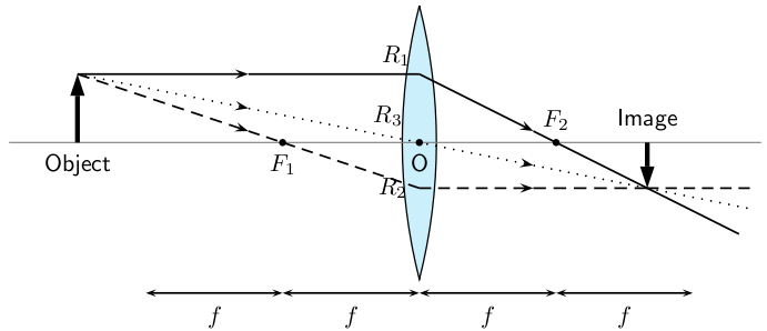
CASE 1: Object placed at a distance greater than 2 f From the lens

An object is placed at a distance greater than 2 f away from the converging lens. Three rays are drawn to locate the image, which is real, and smaller than the object and inverted.

We can locate the position of the image by drawing our three rays. R 1 travels from the object to the lens parallel to the principal axis, is bent by the lens and then travels through the focal point. R 2 passes through the focal point before it enters the lens and therefore must leave the lens parallel to the principal axis. R 3 travels through the center of the lens and does not change direction. The point where R 1 , R 2 and R 3 intersect is the image of the point where they all started.

The image of an object placed at a distance greater than 2 f from the lens is upside down or inverted . This is because the rays which began at the top of the object, above the principal axis, after passing through the lens end up below the principal axis. The image is called a real image because it is on the opposite side of the lens to the object and you can trace all the light rays directly from the image back to the object.

The image is also smaller than the object and is located closer to the lens than the object.

In reality, light rays come from all points along the length of the object. In ray diagrams we only draw three rays (all starting at the top of the object) to keep the diagram clear and simple.

Get Jobilize Job Search Mobile App in your pocket Now!

Get it on Google Play Download on the App Store Now


Source:  OpenStax, Siyavula textbooks: grade 11 physical science. OpenStax CNX. Jul 29, 2011 Download for free at http://cnx.org/content/col11241/1.2
Google Play and the Google Play logo are trademarks of Google Inc.

Notification Switch

Would you like to follow the 'Siyavula textbooks: grade 11 physical science' conversation and receive update notifications?

Ask