| << Chapter < Page | Chapter >> Page > |
Now that you know how to handle simple series and parallel circuits, you are ready to tackle problems like this:
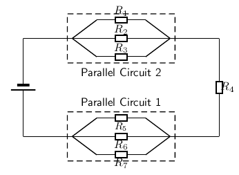
It is relatively easy to work out these kind of circuits because you use everything you have already learnt about series and parallel circuits. The only difference is that you do it in stages. In [link] , the circuit consists of 2 parallel portions that are then in series with 1 resistor. So, in order to work out the equivalent resistance, you start by calculating the total resistance of the parallel portions and then add up all the resistances in series. If all the resistors in [link] had resistances of 10 , we can calculate the equivalent resistance of the entire circuit.
We start by calculating the total resistance of Parallel Circuit 1 .
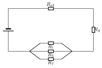
The value of is:
We can similarly calculate the total resistance of Parallel Circuit 2 :
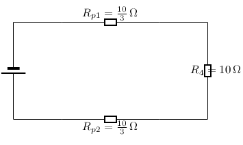
This has now being simplified to a simple series circuit and the equivalent resistance is:
The equivalent resistance of the circuit in [link] is 7,66 .
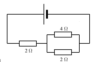
Determine the equivalent resistance of the following circuits:
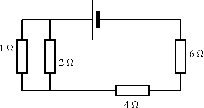
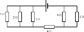
Another method of finding an unknown resistance is to use a Wheatstone bridge . A Wheatstone bridge is a measuring instrument that is used to measure an unknown electrical resistance by balancing two legs of a bridge circuit, one leg of which includes the unknown component. Its operation is similar to the original potentiometer except that in potentiometer circuits the meter used is a sensitive galvanometer.
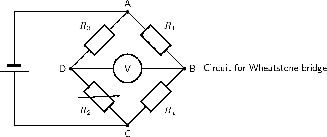
In the circuit of the Wheatstone bridge, is the unknown resistance. , and are resistors of known resistance and the resistance of is adjustable. If the ratio of : is equal to the ratio of : , then the voltage between the two midpoints will be zero and no current will flow between the midpoints. In order to determine the unknown resistance, is varied until this condition is reached. That is when the voltmeter reads 0 V.
What is the resistance of the unknown resistor in the diagram below if =4 =8 and =6 .
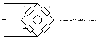
The arrangement is a Wheatstone bridge. So we use the equation:
The resistance of the unknown resistor is 12 .
In addition to voltage and current, there is another measure of free electron activity in a circuit: power . Power is a measure of how rapidly a standard amount of work is done. In electric circuits, power is a function of both voltage and current:
Electrical power is calculated as:

Notification Switch
Would you like to follow the 'Siyavula textbooks: grade 11 physical science' conversation and receive update notifications?