| << Chapter < Page | Chapter >> Page > |
Induction is the process in which an emf is induced by changing magnetic flux. Many examples have been discussed so far, some more effective than others. Transformers, for example, are designed to be particularly effective at inducing a desired voltage and current with very little loss of energy to other forms. Is there a useful physical quantity related to how “effective” a given device is? The answer is yes, and that physical quantity is called inductance .
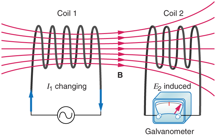
Mutual inductance is the effect of Faraday’s law of induction for one device upon another, such as the primary coil in transmitting energy to the secondary in a transformer. See [link] , where simple coils induce emfs in one another.

In the many cases where the geometry of the devices is fixed, flux is changed by varying current. We therefore concentrate on the rate of change of current, , as the cause of induction. A change in the current in one device, coil 1 in the figure, induces an in the other. We express this in equation form as
where is defined to be the mutual inductance between the two devices. The minus sign is an expression of Lenz’s law. The larger the mutual inductance , the more effective the coupling. For example, the coils in [link] have a small compared with the transformer coils in [link] . Units for are , which is named a henry (H), after Joseph Henry. That is, .
Nature is symmetric here. If we change the current in coil 2, we induce an in coil 1, which is given by
where is the same as for the reverse process. Transformers run backward with the same effectiveness, or mutual inductance .
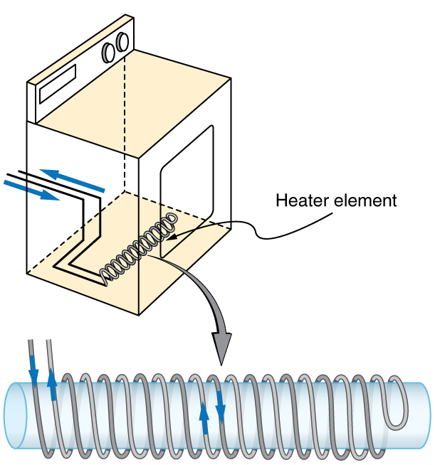
A large mutual inductance may or may not be desirable. We want a transformer to have a large mutual inductance. But an appliance, such as an electric clothes dryer, can induce a dangerous emf on its case if the mutual inductance between its coils and the case is large. One way to reduce mutual inductance is to counterwind coils to cancel the magnetic field produced. (See [link] .)

Self-inductance , the effect of Faraday’s law of induction of a device on itself, also exists. When, for example, current through a coil is increased, the magnetic field and flux also increase, inducing a counter emf, as required by Lenz’s law. Conversely, if the current is decreased, an emf is induced that opposes the decrease. Most devices have a fixed geometry, and so the change in flux is due entirely to the change in current through the device. The induced emf is related to the physical geometry of the device and the rate of change of current. It is given by

Notification Switch
Would you like to follow the 'College physics' conversation and receive update notifications?