| << Chapter < Page | Chapter >> Page > |
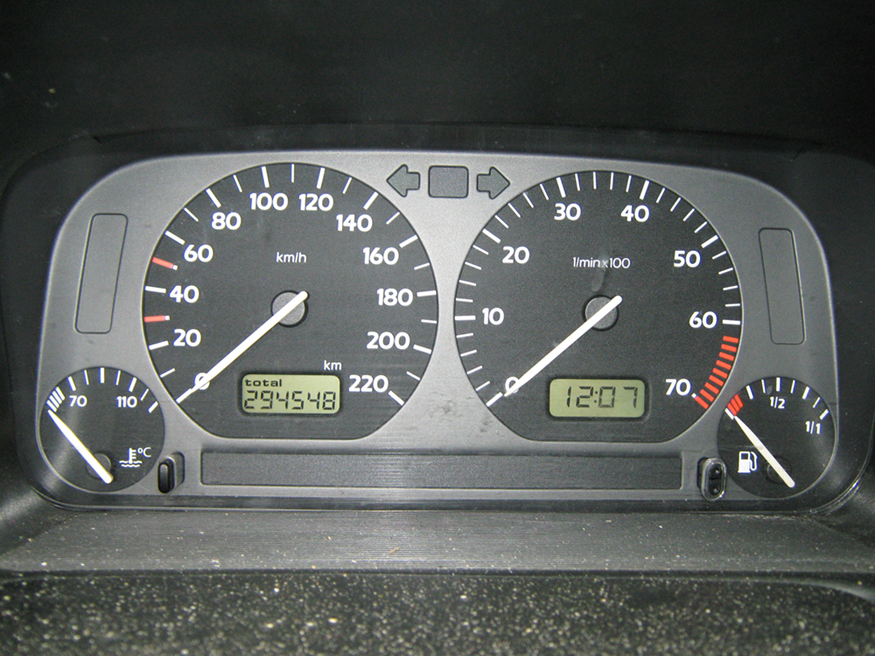
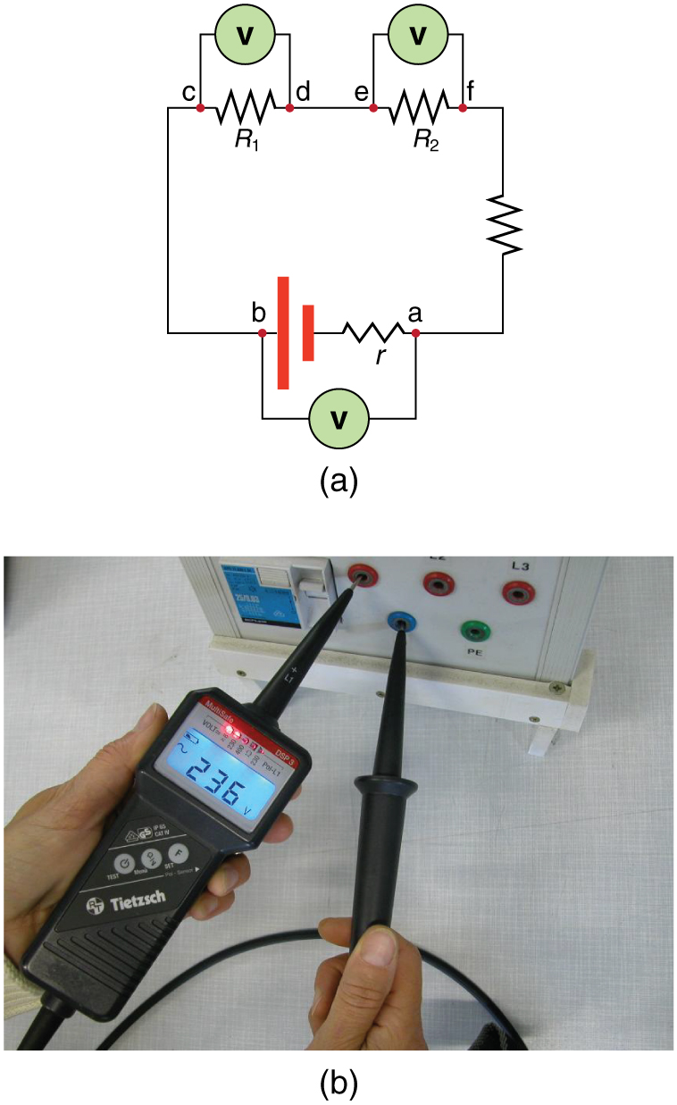
Voltmeters measure voltage, whereas ammeters measure current. Some of the meters in automobile dashboards, digital cameras, cell phones, and tuner-amplifiers are voltmeters or ammeters. (See [link] .) The internal construction of the simplest of these meters and how they are connected to the system they monitor give further insight into applications of series and parallel connections.

Voltmeters are connected in parallel with whatever device’s voltage is to be measured. A parallel connection is used because objects in parallel experience the same potential difference. (See [link] , where the voltmeter is represented by the symbol V.)
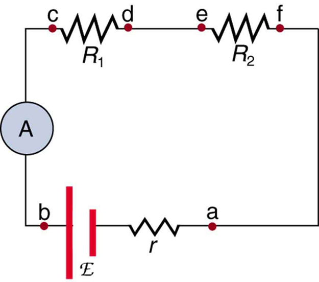
Ammeters are connected in series with whatever device’s current is to be measured. A series connection is used because objects in series have the same current passing through them. (See [link] , where the ammeter is represented by the symbol A.)


Analog meters have a needle that swivels to point at numbers on a scale, as opposed to digital meters , which have numerical readouts similar to a hand-held calculator. The heart of most analog meters is a device called a galvanometer , denoted by G. Current flow through a galvanometer, , produces a proportional needle deflection. (This deflection is due to the force of a magnetic field upon a current-carrying wire.)
The two crucial characteristics of a given galvanometer are its resistance and current sensitivity. Current sensitivity is the current that gives a full-scale deflection of the galvanometer’s needle, the maximum current that the instrument can measure. For example, a galvanometer with a current sensitivity of has a maximum deflection of its needle when flows through it, reads half-scale when flows through it, and so on.

Notification Switch
Would you like to follow the 'College physics' conversation and receive update notifications?