<< Chapter < Page Chapter >> Page >
  • Calculate the total force (magnitude and direction) exerted on a test charge from more than one charge
  • Describe an electric field diagram of a positive point charge; of a negative point charge with twice the magnitude of positive charge
  • Draw the electric field lines between two points of the same charge; between two points of opposite charge.

Drawings using lines to represent electric fields around charged objects are very useful in visualizing field strength and direction. Since the electric field has both magnitude and direction, it is a vector. Like all vectors , the electric field can be represented by an arrow that has length proportional to its magnitude and that points in the correct direction. (We have used arrows extensively to represent force vectors, for example.)

[link] shows two pictorial representations of the same electric field created by a positive point charge Q size 12{Q} {} . [link] (b) shows the standard representation using continuous lines. [link] (b) shows numerous individual arrows with each arrow representing the force on a test charge q size 12{q} {} . Field lines are essentially a map of infinitesimal force vectors.
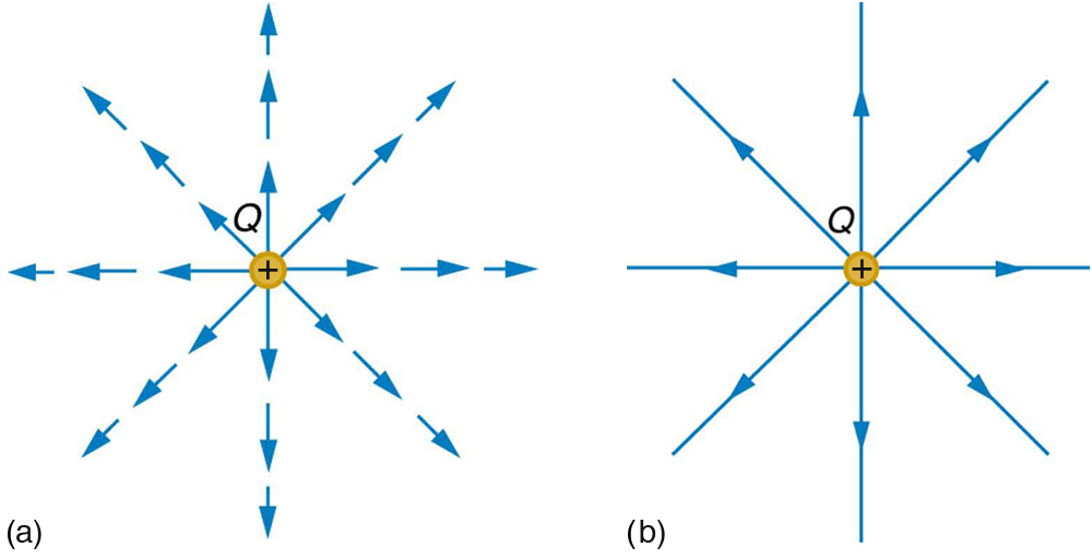
In part a, electric field lines emanating from the charge Q are shown by the vector arrows pointing outward in every direction of two dimensional space. In part b, electric field lines emanating from the charge Q are shown by the vector arrows pointing outward in every direction of two dimensional space.
Two equivalent representations of the electric field due to a positive charge Q size 12{Q} {} . (a) Arrows representing the electric field’s magnitude and direction. (b) In the standard representation, the arrows are replaced by continuous field lines having the same direction at any point as the electric field. The closeness of the lines is directly related to the strength of the electric field. A test charge placed anywhere will feel a force in the direction of the field line; this force will have a strength proportional to the density of the lines (being greater near the charge, for example).

Note that the electric field is defined for a positive test charge q size 12{q} {} , so that the field lines point away from a positive charge and toward a negative charge. (See [link] .) The electric field strength is exactly proportional to the number of field lines per unit area, since the magnitude of the electric field for a point charge is E = k | Q | / r 2 size 12{E= { ital "kQ"} slash {r rSup { size 8{2} } } } {} and area is proportional to r 2 size 12{r rSup { size 8{2} } } {} . This pictorial representation, in which field lines represent the direction and their closeness (that is, their areal density or the number of lines crossing a unit area) represents strength, is used for all fields: electrostatic, gravitational, magnetic, and others.
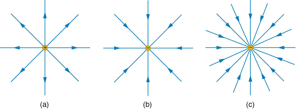
In part a, electric field lines emanating from a positive charge is shown by the vector arrows in all direction of two dimensional space and the density of these field lines is less. In part b, electric field lines entering the negative charge is shown by the vector arrows coming from all direction of two dimensional space and the density of these field lines is less. In part c, electric field lines entering the negative charge is shown by the vector arrows coming from all direction of two dimensional space and the density of these field lines is large.
The electric field surrounding three different point charges. (a) A positive charge. (b) A negative charge of equal magnitude. (c) A larger negative charge.

In many situations, there are multiple charges. The total electric field created by multiple charges is the vector sum of the individual fields created by each charge. The following example shows how to add electric field vectors.

Adding electric fields

Find the magnitude and direction of the total electric field due to the two point charges, q 1 size 12{q rSub { size 8{1} } } {} and q 2 size 12{q rSub { size 8{2} } } {} , at the origin of the coordinate system as shown in [link] .
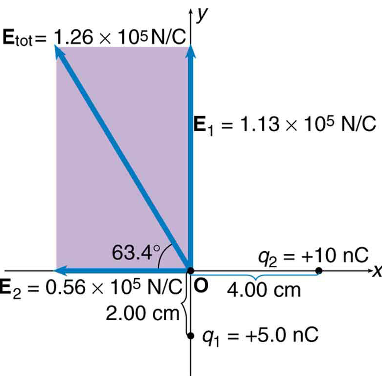
Two charges are placed on a coordinate axes. Q two is at the position x equals 4 and y equals 0 centimeters. Q one is at the position x equals 0 and y equals two centimeters. Charge on q one is plus five point zero nano coulomb and charge on q two is plus ten nano coulomb. The electric field, E one having a magnitude of one point one three multiplied by ten raise to the power five Newton per coulomb is represented by a vector arrow along positive y axis starting from the origin. The electric field, E two having magnitude zero point five six multiplied by ten raise to the power five Newton per coulomb is represented by a vector arrow along negative x axis starting from the origin. The resultant field makes an angle of sixty three point four degree above the negative y axis having magnitude one point two six multiplied by ten raise to the power five Newton per coulomb is represented by a vector arrow pointing away from the origin in the second quadrant.
The electric fields E 1 size 12{E rSub { size 8{1} } } {} and E 2 size 12{E rSub { size 8{2} } } {} at the origin O add to E tot size 12{E rSub { size 8{"tot"} } } {} .

Strategy

Since the electric field is a vector (having magnitude and direction), we add electric fields with the same vector techniques used for other types of vectors. We first must find the electric field due to each charge at the point of interest, which is the origin of the coordinate system (O) in this instance. We pretend that there is a positive test charge, q size 12{q} {} , at point O, which allows us to determine the direction of the fields E 1 size 12{E rSub { size 8{1} } } {} and E 2 size 12{E rSub { size 8{2} } } {} . Once those fields are found, the total field can be determined using vector addition    .

Questions & Answers

what is the anterior
Tito Reply
Means front part of the body
Ibrahim
what is anatomy
Ruth Reply
To better understand how the different part of the body works. To understand the physiology of the various structures in the body. To differentiate the systems of the human body .
Roseann Reply
what is hypogelersomia
aliyu Reply
what are the parts of the female reproductive system?
Orji Reply
what is anatomy
Divinefavour Reply
what are the six types of synovial joints and their ligaments
Darlington Reply
draw the six types of synovial joint and their ligaments
Darlington
System of human beings
Katumi Reply
System in humans body
Katumi
Diagram of animals and plants cell
Favour Reply
at what age does development of bone end
Alal Reply
how many bones are in the human upper layers
Daniel Reply
how many bones do we have
Nbeke
bones that form the wrist
Priscilla Reply
yes because it is in the range of neutrophil count
Alexander Reply
because their basic work is to fight against harmful external bodies and they are always present when chematoxin are released in an area in body
Alexander
What is pathology
Samuel Reply
what is pathology
Nbeke
what's pathology
Nbeke
what is anatomy
ESTHER Reply
what is plasma and is component
Fad Reply
Got questions? Join the online conversation and get instant answers!
Jobilize.com Reply
Practice Key Terms 4

Get Jobilize Job Search Mobile App in your pocket Now!

Get it on Google Play Download on the App Store Now


Source:  OpenStax, College physics. OpenStax CNX. Jul 27, 2015 Download for free at http://legacy.cnx.org/content/col11406/1.9
Google Play and the Google Play logo are trademarks of Google Inc.

Notification Switch

Would you like to follow the 'College physics' conversation and receive update notifications?

Ask