| << Chapter < Page | Chapter >> Page > |
By the end of this section, you will be able to:
Standard measurements of voltage and current alter the circuit being measured, introducing uncertainties in the measurements. Voltmeters draw some extra current, whereas ammeters reduce current flow. Null measurements balance voltages so that there is no current flowing through the measuring device and, therefore, no alteration of the circuit being measured.
Null measurements are generally more accurate but are also more complex than the use of standard voltmeters and ammeters, and they still have limits to their precision. In this module, we shall consider a few specific types of null measurements, because they are common and interesting, and they further illuminate principles of electric circuits.
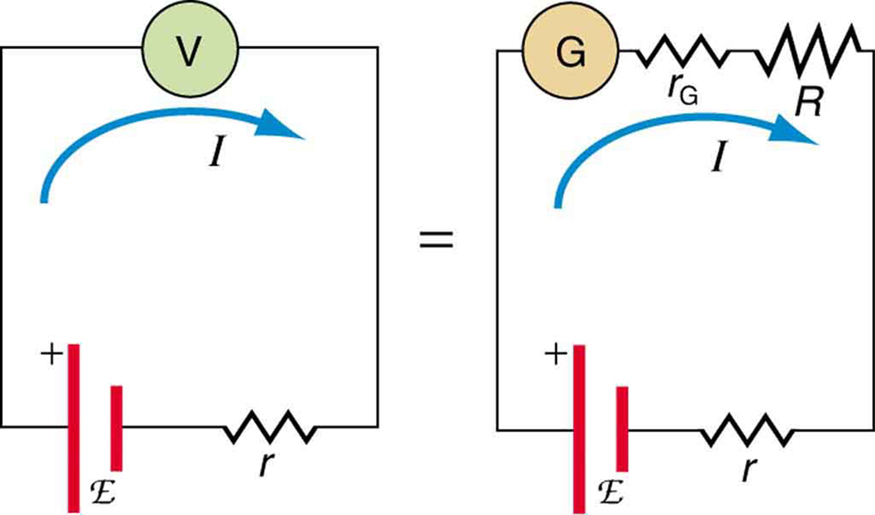
Suppose you wish to measure the emf of a battery. Consider what happens if you connect the battery directly to a standard voltmeter as shown in [link] . (Once we note the problems with this measurement, we will examine a null measurement that improves accuracy.) As discussed before, the actual quantity measured is the terminal voltage , which is related to the emf of the battery by , where is the current that flows and is the internal resistance of the battery.
The emf could be accurately calculated if were very accurately known, but it is usually not. If the current could be made zero, then , and so emf could be directly measured. However, standard voltmeters need a current to operate; thus, another technique is needed.

A potentiometer is a null measurement device for measuring potentials (voltages). (See [link] .) A voltage source is connected to a resistor say, a long wire, and passes a constant current through it. There is a steady drop in potential (an drop) along the wire, so that a variable potential can be obtained by making contact at varying locations along the wire.
[link] (b) shows an unknown (represented by script in the figure) connected in series with a galvanometer. Note that opposes the other voltage source. The location of the contact point (see the arrow on the drawing) is adjusted until the galvanometer reads zero. When the galvanometer reads zero, , where is the resistance of the section of wire up to the contact point. Since no current flows through the galvanometer, none flows through the unknown emf, and so is directly sensed.
Now, a very precisely known standard is substituted for , and the contact point is adjusted until the galvanometer again reads zero, so that . In both cases, no current passes through the galvanometer, and so the current through the long wire is the same. Upon taking the ratio , cancels, giving

Notification Switch
Would you like to follow the 'College physics for ap® courses' conversation and receive update notifications?