<< Chapter < Page Chapter >> Page >

Learning objectives

By the end of this section, you will be able to:

  • Calculate emf, force, magnetic field, and work due to the motion of an object in a magnetic field.

As we have seen, any change in magnetic flux induces an emf opposing that change—a process known as induction. Motion is one of the major causes of induction. For example, a magnet moved toward a coil induces an emf, and a coil moved toward a magnet produces a similar emf. In this section, we concentrate on motion in a magnetic field that is stationary relative to the Earth, producing what is loosely called motional emf .

One situation where motional emf occurs is known as the Hall effect and has already been examined. Charges moving in a magnetic field experience the magnetic force F = qvB sin θ size 12{F= ital "qvB""sin"θ} {} , which moves opposite charges in opposite directions and produces an emf = Bℓv size 12{"emf"=Bℓv} {} . We saw that the Hall effect has applications, including measurements of B size 12{B} {} and v size 12{v} {} . We will now see that the Hall effect is one aspect of the broader phenomenon of induction, and we will find that motional emf can be used as a power source.

Consider the situation shown in [link] . A rod is moved at a speed v along a pair of conducting rails separated by a distance in a uniform magnetic field B size 12{B} {} . The rails are stationary relative to B size 12{B} {} and are connected to a stationary resistor R size 12{R} {} . The resistor could be anything from a light bulb to a voltmeter. Consider the area enclosed by the moving rod, rails, and resistor. B size 12{B} {} is perpendicular to this area, and the area is increasing as the rod moves. Thus the magnetic flux enclosed by the rails, rod, and resistor is increasing. When flux changes, an emf is induced according to Faraday’s law of induction.
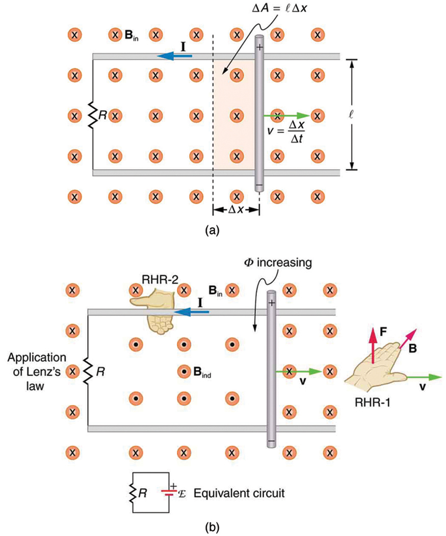
Part a of the figure shows two parallel rails held horizontal at distance l apart in a uniform magnetic field B in, directed toward the plane of the paper. A resistance R is connected at one of its ends. A rod is kept vertical at the middle on the rails and moved toward the right for a distance delta x with a velocity v. the velocity v is given by delta x divided by delta t. The rectangular area enclosed between the initial position of the rod and the final position after a movement of delta x is given as delta A equals l multiplied by delta x. There is a current induced, I in the upper rail toward left. The upper end of the rod is shown positive and the lower end negative. Part b of the diagram shows the same arrangement as in part a. Two parallel rails held horizontal at distance l apart in a uniform magnetic field B in, directed toward the plane of the paper. A resistance is connected at one of its ends. A rod is kept vertical at the middle on the rails and moved toward the right a distance delta x with a velocity v. Lenz’s law is applied and the direction of induced field and current is shown. There is a current induced I in the upper rail toward left. The upper end of the rod is shown positive and the lower end negative. The induced field B ind is shown in the area enclosed between the resistance R, the rod and the rails. The induced field is opposite to the applied field. The induced field points away from the paper. The flux phi is shown increasing in the enclosed area. A picture of the right hand with its fingers and thumb stretched is shown toward the right of the image to explain the right hand rule. An equivalent circuit of the above figure is shown to be equivalent to a cell of e m f connected across a resistance R.
(a) A motional emf = Bℓv size 12{"emf"=Bℓv} {} is induced between the rails when this rod moves to the right in the uniform magnetic field. The magnetic field B size 12{B} {} is into the page, perpendicular to the moving rod and rails and, hence, to the area enclosed by them. (b) Lenz’s law gives the directions of the induced field and current, and the polarity of the induced emf. Since the flux is increasing, the induced field is in the opposite direction, or out of the page. RHR-2 gives the current direction shown, and the polarity of the rod will drive such a current. RHR-1 also indicates the same polarity for the rod. (Note that the script E symbol used in the equivalent circuit at the bottom of part (b) represents emf.)

To find the magnitude of emf induced along the moving rod, we use Faraday’s law of induction without the sign:

emf = N Δ Φ Δ t . size 12{"emf"=N { {ΔΦ} over {Δt} } } {}

Here and below, “emf” implies the magnitude of the emf. In this equation, N = 1 size 12{N=1} {} and the flux Φ = BA cos θ size 12{Φ= ital "BA""cos"θ} {} . We have θ = and cos θ = 1 , since B is perpendicular to A . Now Δ Φ = Δ ( BA ) = B Δ A size 12{ΔΦ=Δ \( ital "BA" \) =BΔA} {} , since B size 12{B} {} is uniform. Note that the area swept out by the rod is Δ A = Δ x size 12{ΔA=ℓΔx} {} . Entering these quantities into the expression for emf yields

emf = B Δ A Δ t = B Δ x Δ t . size 12{"emf"= { {BΔA} over {Δt} } =B { {ℓΔx} over {Δt} } } {}

Finally, note that Δ x / Δ t = v size 12{Δx/Δt=v} {} , the velocity of the rod. Entering this into the last expression shows that

emf = Bℓv ( B , ℓ, and v perpendicular) size 12{"emf"=Bℓv} {}

is the motional emf. This is the same expression given for the Hall effect previously.

Get Jobilize Job Search Mobile App in your pocket Now!

Get it on Google Play Download on the App Store Now


Source:  OpenStax, College physics for ap® courses. OpenStax CNX. Nov 04, 2016 Download for free at https://legacy.cnx.org/content/col11844/1.14
Google Play and the Google Play logo are trademarks of Google Inc.

Notification Switch

Would you like to follow the 'College physics for ap® courses' conversation and receive update notifications?

Ask