| << Chapter < Page | Chapter >> Page > |
SSPD_Chapter 7_Part3_Basic Electrical Properties of MOScontinued5.
7.3.12. Optimization of geometric parameters to achieve best ciruit performance of CMOS inverter.
We have seen in Section 7.3.3.1 that in triode region the drain current is:


In pentode region the drain current is:


Therefore:

Where

For NMOS:

For PMOS:

Referring to Figure 7.3.11.3.(c) we see that CMOS has five regions of operation:
Region 1: I/P=LOW and O/P=HIGH, PMOS is fully ON and NMOS is fully OFF and O/P is connected to V DD through ON PMOS. Full logic ‘1’ voltage is available at the O/P.
Region 5: I/P=HIGH and O/P=LOW, PMOS is fully OFF and NMOS is fully ON and O/P is connected to GND through ON NMOS. Full logic ‘0’ voltage is available at the O/P.
Region 2: Transition region. PMOS is in triode region and NMOS is in Pentode region. Therefore:


Region 4: Transition region. PMOS is in pentode region and NMOS is in trode region.
Therefore


Region 3: Transtion region and both MOSs are in saturation region.
Therefore


For PMOS: V GS = V in – V DD since source of PMOS is connected to positive bus.
For NMOS: V GS = V in since source of NMOS is connected to GND bus.
Therefore


In region 3, when ON state is being transferred from one MOS to another then maximum current flows between the rails and since the two MOS are in series hence


Therefore:

Manipulating the terms we get:

Square root of k 2 gives two solutions:

The positive solution of k gives a physically untenable result:

This is physically untenable because at k = 1 we get unacceptable result for V in .
The negative solution of k gives an acceptable value of V in :

Or

If

and the two transistors are of equal magnitude threshold voltage that is:

then

This implies that the switch over is symmetrically disposed about the point :

To achieve a symmetrical transfer curve it is necessary that

And

This implies that

Or

As discussed in the preceding section, inorder to get optimum performance in switching speed as well as in transfer curve PMOS will have to be wider than NMOS.
In VLSI Technology, as the dimensions are being scaled short channel effects are showing up. One of the short channel effects is electric drift mobility dependence on longitudinal and transverse electric field.
Reference [“The dependence of the electron mobility on the longitudinal electric field in MOSFETs” by J.B.Rolden et al,Semiconductor Science Technology, Vol 12,(1997),321-330] gives the following relationship:


Pucknell et. al. gives the following expression:

Where φ = constant of the range 0.05;
V t = threshold voltage including the body effect;
And µ Z = drift mobility with zero transverse electric field.
V GS /D = decides the transverse electric field;
D = gate oxide thickness.
Since mobility has transverse electric field dependence hence only at the symmetry point, k = 1 hold good.
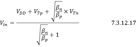
As can be seen from Eq.7.3.12.17, at V out =V DD /2 , V in = V DD /2 only at k = 1.

The relation ship is :

is satisfied.
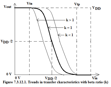
If due to manufacturing tolerance k<1 then according to Eq.7.3.12.17,

If k>1

We get a similar kind of lateral shift in the transfer characteristics as shown in Figure 7.3.12.1.

As can be recognized that the symmetry point is:

is inherently a unstable point hence the changeover from HIGH to LOW or vica versa is rapid and only

Or

are the two stable operating points.
Now we will look at the circuit model of CMOS.

Notification Switch
Would you like to follow the 'Solid state physics and devices-the harbinger of third wave of civilization' conversation and receive update notifications?