<< Chapter < Page Chapter >> Page >
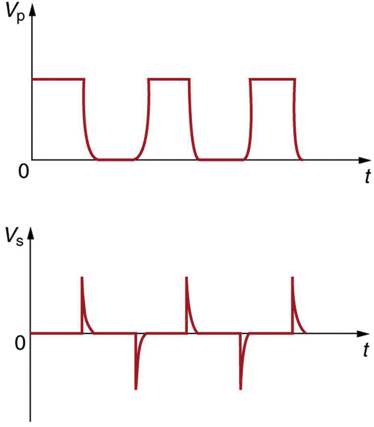
The first part of the figure shows a graph of DC voltage input. The graph shows a variation of voltage V p along the Y axis and time t along the X axis. The wave is a pulsed wave nearly square in nature with the vibrations only in positive half cycle. The negative half cycles are not present in the wave. The second part of the figure shows a spike wave graph. The graph shows a variation of voltage V s along the Y axis and time t along the X axis. The wave has both positive and negative half cycles shown as sharp spikes of uniform amplitude.
Transformers do not work for pure DC voltage input, but if it is switched on and off as on the top graph, the output will look something like that on the bottom graph. This is not the sinusoidal AC most AC appliances need.

Calculating characteristics of a step-down transformer

A battery charger meant for a series connection of ten nickel-cadmium batteries (total emf of 12.5 V DC) needs to have a 15.0 V output to charge the batteries. It uses a step-down transformer with a 200-loop primary and a 120 V input. (a) How many loops should there be in the secondary coil? (b) If the charging current is 16.0 A, what is the input current?

Strategy and Solution for (a)

You would expect the secondary to have a small number of loops. Solving V s V p = N s N p size 12{ { {V rSub { size 8{s} } } over {V rSub { size 8{p} } } } = { {N rSub { size 8{s} } } over {N rSub { size 8{p} } } } } {} for N s size 12{N rSub { size 8{s} } } {} and entering known values gives

N s = N p V s V p = ( 200 ) 15 . 0 V 120 V = 25 . alignl { stack { size 12{N rSub { size 8{s} } =N rSub { size 8{p} } { {V rSub { size 8{s} } } over {V rSub { size 8{p} } } } } {} #" "= \( "200" \) { {"15" "." "0 V"} over {"120 V"} } ="25" {} } } {}

Strategy and Solution for (b)

The current input can be obtained by solving I s I p = N p N s size 12{ { {I rSub { size 8{s} } } over {I rSub { size 8{p} } } } = { {N rSub { size 8{p} } } over {N rSub { size 8{s} } } } } {} for I p size 12{I rSub { size 8{p} } } {} and entering known values. This gives

I p = I s N s N p = ( 16 . 0 A ) 25 200 = 2 . 00 A . alignl { stack { size 12{I rSub { size 8{p} } =I rSub { size 8{s} } { {N rSub { size 8{s} } } over {N rSub { size 8{p} } } } } {} #" "= \( "16" "." "0 A" \) { {"25"} over {"200"} } =2 "." "00"" A" {} } } {}

Discussion

The number of loops in the secondary is small, as expected for a step-down transformer. We also see that a small input current produces a larger output current in a step-down transformer. When transformers are used to operate large magnets, they sometimes have a small number of very heavy loops in the secondary. This allows the secondary to have low internal resistance and produce large currents. Note again that this solution is based on the assumption of 100% efficiency—or power out equals power in ( P p = P s size 12{P rSub { size 8{p} } =P rSub { size 8{s} } } {} )—reasonable for good transformers. In this case the primary and secondary power is 240 W. (Verify this for yourself as a consistency check.) Note that the Ni-Cd batteries need to be charged from a DC power source (as would a 12 V battery). So the AC output of the secondary coil needs to be converted into DC. This is done using something called a rectifier, which uses devices called diodes that allow only a one-way flow of current.

Transformers have many applications in electrical safety systems, which are discussed in Electrical Safety: Systems and Devices .

Phet explorations: generator

Generate electricity with a bar magnet! Discover the physics behind the phenomena by exploring magnets and how you can use them to make a bulb light.

Generator

Section summary

  • Transformers use induction to transform voltages from one value to another.
  • For a transformer, the voltages across the primary and secondary coils are related by
    V s V p = N s N p , size 12{ { {V rSub { size 8{s} } } over {V rSub { size 8{p} } } } = { {N rSub { size 8{s} } } over {N rSub { size 8{p} } } } } {}
    where V p size 12{V rSub { size 8{p} } } {} and V s size 12{V rSub { size 8{s} } } {} are the voltages across primary and secondary coils having N p size 12{N rSub { size 8{p} } } {} and N s size 12{N rSub { size 8{s} } } {} turns.
  • The currents I p size 12{I rSub { size 8{p} } } {} and I s size 12{I rSub { size 8{s} } } {} in the primary and secondary coils are related by I s I p = N p N s size 12{ { {I rSub { size 8{s} } } over {I rSub { size 8{p} } } } = { {N rSub { size 8{p} } } over {N rSub { size 8{s} } } } } {} .
  • A step-up transformer increases voltage and decreases current, whereas a step-down transformer decreases voltage and increases current.

Conceptual questions

Explain what causes physical vibrations in transformers at twice the frequency of the AC power involved.

Problems&Exercises

A plug-in transformer, like that in [link] , supplies 9.00 V to a video game system. (a) How many turns are in its secondary coil, if its input voltage is 120 V and the primary coil has 400 turns? (b) What is its input current when its output is 1.30 A?

(a) 30.0

(b) 9 . 75 × 10 2 A size 12{9 "." "75" times "10" rSup { size 8{ - 2} } `A} {}

Practice Key Terms 4

Get Jobilize Job Search Mobile App in your pocket Now!

Get it on Google Play Download on the App Store Now


Source:  OpenStax, General physics ii phy2202ca. OpenStax CNX. Jul 05, 2013 Download for free at http://legacy.cnx.org/content/col11538/1.2
Google Play and the Google Play logo are trademarks of Google Inc.

Notification Switch

Would you like to follow the 'General physics ii phy2202ca' conversation and receive update notifications?

Ask