| << Chapter < Page | Chapter >> Page > |
Wireline channels were the first used for electrical communications in the mid-nineteenth century for the telegraph.Here, the channel is one of several wires connecting transmitter to receiver. The transmitter simply creates a voltage relatedto the message signal and applies it to the wire(s). We must have a circuit—a closed path—that supports current flow. In thecase of single-wire communications, the earth is used as the current's return path. In fact, the term ground for the reference node in circuits originated in single-wire telegraphs. You can imagine that the earth's electricalcharacteristics are highly variable, and they are. Single-wire metallic channels cannot support high-quality signaltransmission having a bandwidth beyond a few hundred Hertz over any appreciable distance.

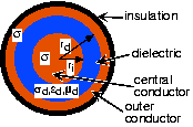
Consequently, most wireline channels today essentially consist of pairs of conducting wires ( [link] ), and the transmitter applies a message-related voltage across the pair. How these pairs of wires arephysically configured greatly affects their transmission characteristics. One example is twisted pair , wherein the wires are wrapped about each other. Telephonecables are one example of a twisted pair channel. Another is coaxial cable , where a concentric conductor surrounds a central wire with a dielectric material in between.Coaxial cable, fondly called "co-ax" by engineers, is what Ethernet uses as its channel. In either case, wireline channelsform a dedicated circuit between transmitter and receiver. As we shall find subsequently, several transmissions can share thecircuit by amplitude modulation techniques; commercial cable TV is an example. These information-carrying circuits are designedso that interference from nearby electromagnetic sources is minimized. Thus, by the time signals arrive at the receiver,they are relatively interference- and noise-free.
Both twisted pair and co-ax are examples of
transmission
lines , which all have the circuit model shown in
[link] for an infinitesimally small length. This circuit model arisesfrom solving Maxwell's equations for the particular
transmission line geometry.
Circuit model for a transmission line


Notification Switch
Would you like to follow the 'Fundamentals of electrical engineering i' conversation and receive update notifications?