<< Chapter < Page Chapter >> Page >
  • Describe the use of heat engines in heat pumps and refrigerators.
  • Demonstrate how a heat pump works to warm an interior space.
  • Explain the differences between heat pumps and refrigerators.
  • Calculate a heat pump’s coefficient of performance.
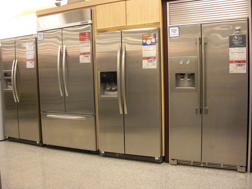
Photograph of various expensive refrigerators displayed in a home appliance store.
Almost every home contains a refrigerator. Most people don’t realize they are also sharing their homes with a heat pump. (credit: Id1337x, Wikimedia Commons)

Heat pumps, air conditioners, and refrigerators utilize heat transfer from cold to hot. They are heat engines run backward. We say backward, rather than reverse, because except for Carnot engines, all heat engines, though they can be run backward, cannot truly be reversed. Heat transfer occurs from a cold reservoir Q c size 12{Q rSub { size 8{c} } } {} and into a hot one. This requires work input W size 12{W} {} , which is also converted to heat transfer. Thus the heat transfer to the hot reservoir is Q h = Q c + W size 12{Q rSub { size 8{h} } =Q rSub { size 8{c} } +W} {} . (Note that Q h size 12{Q rSub { size 8{h} } } {} , Q c size 12{Q rSub { size 8{c} } } {} , and W size 12{W} {} are positive, with their directions indicated on schematics rather than by sign.) A heat pump’s mission is for heat transfer Q h size 12{Q rSub { size 8{h} } } {} to occur into a warm environment, such as a home in the winter. The mission of air conditioners and refrigerators is for heat transfer Q c size 12{Q rSub { size 8{c} } } {} to occur from a cool environment, such as chilling a room or keeping food at lower temperatures than the environment. (Actually, a heat pump can be used both to heat and cool a space. It is essentially an air conditioner and a heating unit all in one. In this section we will concentrate on its heating mode.)
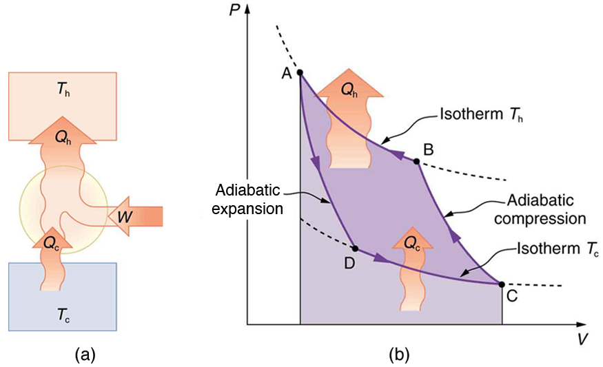
Part a of the figure shows a heat pump, drawn as a circle. Work W, indicated by a bold orange arrow, is put in to to the pump to transfer heat Q sub c, indicated by a bold orange arrow, out of a cold temperature reservoir T sub c, drawn as a blue rectangle, and pumps heat Q sub h, indicated by a larger bold orange arrow, into high temperature reservoir T sub h. Part b of the figure shows a P V diagram for a Carnot cycle. The pressure P is along the Y axis and the volume V is along the X axis. The graph shows a complete cycle A D C B A. The path begins at point A, then it drops sharply down and slightly to the right until point D. This is marked as an adiabatic expansion. Then the curve drops down more gradually, still to the right, from point D to point C. This is marked as an isotherm at temperature T sub c, during which heat Q sub c enters the system. The curve then rises from point C to point B along the direction opposite to that of A D. This is an adiabatic compression. The last part of the curve rises up from point B back to A. This is marked as an isotherm at temperature T sub h, during which heat Q sub h leaves the system. The path D C is lower than path B A. Heat entering and leaving the system is indicated by bold orange arrows, with Q sub h larger than Q sub c.
Heat pumps, air conditioners, and refrigerators are heat engines operated backward. The one shown here is based on a Carnot (reversible) engine. (a) Schematic diagram showing heat transfer from a cold reservoir to a warm reservoir with a heat pump. The directions of W size 12{W} {} , Q h size 12{Q rSub { size 8{h} } } {} , and Q c size 12{Q rSub { size 8{c} } } {} are opposite what they would be in a heat engine. (b) PV size 12{ ital "PV"} {} diagram for a Carnot cycle similar to that in [link] but reversed, following path ADCBA. The area inside the loop is negative, meaning there is a net work input. There is heat transfer Q c size 12{Q rSub { size 8{c} } } {} into the system from a cold reservoir along path DC, and heat transfer Q h size 12{Q rSub { size 8{h} } } {} out of the system into a hot reservoir along path BA.

Heat pumps

The great advantage of using a heat pump to keep your home warm, rather than just burning fuel, is that a heat pump supplies Q h = Q c + W size 12{Q rSub { size 8{h} } =Q rSub { size 8{c} } +W} {} . Heat transfer is from the outside air, even at a temperature below freezing, to the indoor space. You only pay for W size 12{W} {} , and you get an additional heat transfer of Q c size 12{Q rSub { size 8{c} } } {} from the outside at no cost; in many cases, at least twice as much energy is transferred to the heated space as is used to run the heat pump. When you burn fuel to keep warm, you pay for all of it. The disadvantage is that the work input (required by the second law of thermodynamics) is sometimes more expensive than simply burning fuel, especially if the work is done by electrical energy.

The basic components of a heat pump in its heating mode are shown in [link] . A working fluid such as a non-CFC refrigerant is used. In the outdoor coils (the evaporator), heat transfer Q c size 12{Q rSub { size 8{c} } } {} occurs to the working fluid from the cold outdoor air, turning it into a gas.

Practice Key Terms 2

Get Jobilize Job Search Mobile App in your pocket Now!

Get it on Google Play Download on the App Store Now


Source:  OpenStax, College physics (engineering physics 2, tuas). OpenStax CNX. May 08, 2014 Download for free at http://legacy.cnx.org/content/col11649/1.2
Google Play and the Google Play logo are trademarks of Google Inc.

Notification Switch

Would you like to follow the 'College physics (engineering physics 2, tuas)' conversation and receive update notifications?

Ask