| << Chapter < Page | Chapter >> Page > |
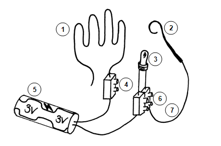
4 Connector – a single connector cut from a strip.
5 3 Volt battery container with wires attached.
6 Connector – double connector cut from strip.
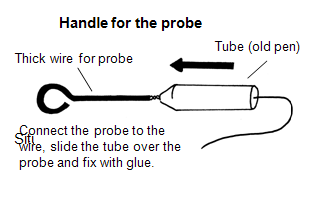
7 Wire – to connect the handle to the circuit.


Situation 2

We are all aware that smoking is bad for ones health. Even passive smokers are greatly harmed by people who smoke in their presence. Use an old medicine bottle to manufacture an anti-smoking sign. The drawing must contain a circuit that will draw the attention of smokers. You can make use of a flickering LED to make the sign more effective.
Assessment
| Learning outcomes(LOs) |
| LO 2 |
| TECHNOLOGICAL KNOWLEDGE AND UNDERSTANDINGThe learner will be able to understand and apply relevant technological knowledge ethically and responsibly. |
| This is demonstrated when the learner: |
| structures:2.1 demonstrate knowledge and understanding of frame structures:the use and application of basic structural components (columns, beams, arches, buttresses, struts, stays, guys, ties);reinforcing techniques for frame structures (triangulation, webs and fillets, orientation and cross-sectional area and members);how frame structures can be made strong (e.g. relationship between the size and the shape of the base, the centre of gravity and stability;systems and control:2.4 demonstrates knowledge and understanding of how electrical circuits with more than one input or control device will work based on different logic conditions (“AND” and “OR” logic), and represents them using circuit diagrams, systems diagrams and truth tables. |
Memorandum
Learners have to discover this through practical experience. Many schools still have wooden boards that are suitable for this practical exercise. The breadboards are also very suited, as circuits can be built very quickly. In this instance, LEDs can be used in the place of light bulbs. This also provides an ideal opportunity to use the MultiMate. Learners could take readings while they are working.
Note that the long arm is positive and the short arm negative. The components therefore have to be linked correctly and be protected by a resistor.
Assignment 1
1. a) 1,5 V + 1,5 V = 3 V
b) The output glow is duller.
2. a) 1,5 V
b) No noticeable effect, but battery will discharge faster.Dull
3. a) The others do not glow.
b) All glow more dully.
c) 3 V (if the input is a 3V battery, there is no resistance)
4. a) The other one continues to glow.
b) All will glow equally brightly.
c) 3V (if input is a 3V battery, there is no resistance.)
5. a) It protects the LEDs in the circuit.
b) R1 + R2 = RT (formula for serially-linked resistors)
Focus Task 1:
Soldering:
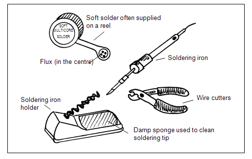
The following sketch illustrates the basic requirements for soldering. The solder is an alloy of lead and tin. It contains its own flux which allows the solder to flow freely.

Situation 1
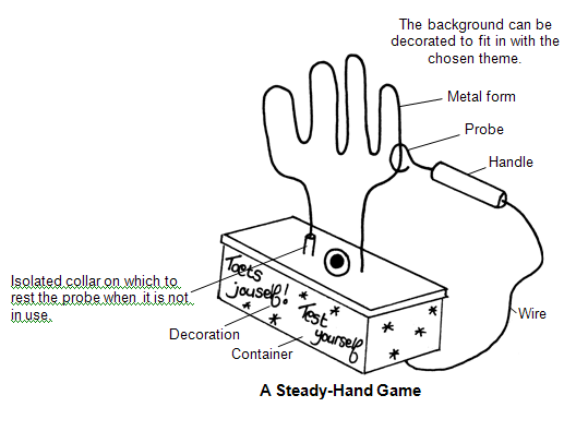
The following examples provide an idea of what the learners' ideas should lead to (a wooden board of 150 mm x 60 mm x 22 mm could be used as a base). If learners wish to add a background, a saw may be used to cut a 3-mm groove in the board, for inserting a piece of hardboard as backing. Motifs that suit the wiring (theme) may be painted on this background, or suitable pictures may be pasted on it.
Situation 2
Learners could make use of waste containers, like plastic bottles, to cut out motives, e.g. a pair of lungs, and draw in details using fibre-tipped pens with permanent colours. The circuit could be built on strip board, using long wires for linking the battery, so that the battery can remain outside the bottle. The circuit board can be inserted into the bottle if the back of the bottle is cut open.
In both instances learners have to identify and formulate the problems that arise in the given situation. They have to write their own design proposals and the educator could stipulate specifications according to the nature of the class, materials, equipment and available components. The learners' ideas might include different circuit layouts as well as different designs. The educator will have to evaluate their models accordingly.
Each learner has to produce a portfolio and design a cover page for it.
The following steps have to be followed during soldering:
Ensure that no movement occurs where the wires are being joined (a "third hand" will be needed).
Heat the join with the soldering iron.
Place some soldering flux on the join.
There should be a shiny join when the wire has cooled down.
Take note:
The surfaces to be joined must be clean.
Allow 3 to 5 seconds for the heating of the join.
Use a soldering iron of appropriate size for your work.
A practical suggestion: When two wires are to be joined by soldering, the two separate ends could be soldered before being joined together — this is known as sweating. Use old printed circuit boards (PCBs) for practising soldering.

Notification Switch
Would you like to follow the 'Technology grade 8' conversation and receive update notifications?