| << Chapter < Page | Chapter >> Page > |
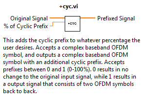
Input/outputs and help

The Cyclic Prefix sub-VI in the OFDM transmitter is shown above in Figure 1. The theory behind the cyclic prefix is rather intuitive. Leading up to this module, we have one complete period of a complex baseband OFDM symbol. However, depending on the channel, we may have significant multipath fading. In order to combat channels with delays, we need a guard interval. This is essentially an interval in the transmission that we will eventually throw out. For more complete treatment on multipath channel models and why guard intervals are effective, Krishna Sankar does a terrific job in his blog entry .
The procedure is very simple. Some percentage of the end of the signal is copied and added to the front. This doesn't create any discontinuities because the next point after the end of the signal is the beginning of the signal since we have exactly one period. Thus any portion of the end of the signal we copy to the front of the signal will add without discontinuity. If this is still difficult to see, imagine copying and pasting a full period of a sine wave to the start, so we now have two periods of that sine wave. Now imagine deleting 1/4 of the points at the beginning of the new signal. It's easy to see that nothing unorthodox is going on here, and you've effectively created a cyclic prefix of 0.5 or 50%. Now it's easy to generalize this to any arbitrary signal, as long as we have exactly one period.
Block diagram layout

Here, Figure 2 shows a LabVIEW implementation of what we just described. It is available for download below. The only subtleties here mainly deal with user friendly-ness. The module accepts a ratio between 0 and 1 representing a percentage between 0 and 100%. We then take the complement of this ratio in order to properly split the array. So our ratio is created by 1-(perc/100). This is because LabVIEW's built in function split array takes as an input the point in the array at which we wish to split. Thus if we want 75% prefix, since we work from the end of the signal and move towards the start, we want to break at the 25% point of the signal and take the second half. This ratio is thus multiplied by the total signal length and the break point is calculated.
The portion that is extracted is then concatenated to the original input signal, and our prefixed signal is complete. One sticking point is to ensure that when the "Build Array" function is invoked, that you right-click the block and choose "Concatenate Inputs" so that the arrays are properly joined. For all general questions, check out the instructional video below in Figure 3, the example use video in Figure 4, or email the author for more information.
Instructional video
Example video

Notification Switch
Would you like to follow the 'Fully configurable ofdm sdr transceiver in labview' conversation and receive update notifications?