| << Chapter < Page | Chapter >> Page > |
Input/outputs and help

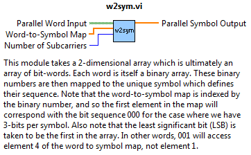
The above Figure (Figure 1) shows the Words-to-Symbols function. This is fairly straightforward: in band limited channels, we cannot send a square-wave stream of 1's and 0's. More importantly, we'd like to leverage OFDM's attractive properties and transmit many data streams on multiple carriers.
Thus we must take each word (itself a group of bits), and assign it a unique complex signal. This is where any popular scheme is chosen such as BPSK, M-ary QAM, etc. By simply defining the word-to-symbol map, the numbers the words represent in the base 10 (decimal) system index elements in the map and the conversion is done.
Block diagram layout

Figure 2 shows this simple process. As an example, let's say the bit-word is 110. LabVIEW's convention would read this as decimal 3, as the first item in the array is seen as the least significant bit (LSB). Next, we index our symbol array with decimal 3. Thus, entry 3 of our word-to-symbol map (which better have 8 unique entries in this example) will be the symbol representing the bit stream 110, say 4+4i. This complex amplitude is then stored in the output stream of parallel words, eventually to occupy an FFT bin.
The only potential pitfall here is the use of indexing. When an array is fed into a for loop, you can right click the entry point and enable indexing. This will present inside the loop the element corresponding to that iteration of the loop. In other words, the first time around, we're going to access the first bit-word (0th element), the second time around the second word etc. In that vein, we also build our output array in the same iterative fashion by indexing it as well.
If you are still confused on how this works, check out the tutorial video below, the example usage video in Figure 4 or email the author for more questions. The sub-VI is available below for download.
Instructional video
Example video

Notification Switch
Would you like to follow the 'Fully configurable ofdm sdr transceiver in labview' conversation and receive update notifications?