| << Chapter < Page | Chapter >> Page > |
The design target of the Lotus Seven S4 (Type 60) was to aimed at meeting several requirements:
The success of the design of the Seven S4, and the choice of various components, should be considered with regard to these goals. As such the S4 was a rather clever piece of design that largely overcame the cost problems of the Seven S3.
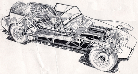
Although the Peter Lucas designed chassis of the Type 60 Seven S4 is basically a mils steel tubular frame design, it is significantly simplified as compared to the proceeding Seven models. Using steel square upper and lower side tubes with triangulation and cross members with square steel tubes, the main chassis was simple in design. A rear frame was made from round tubular steel. The upper rear chassis doubled as the attachment point for the 7 1 / 2 gallon steel fuel tank, the seat belts, and the body to the chassis.
With the elimination of much of the triangulation used in the S2 and S3 models, the rigidity of the S4 was dependent on the presence of two welded side panels made of sheet steel. Further simplification and strength was provided by the front box section being made of folded steel rather than tubular in structure. This followed the fashion of the Lotus Elan and Europa models. A folded steel bulkhead panel was used in place of the usual tubular support. As with the previous Sevens, Arch Motors fabricated the majority of chassis, although Griston Engineering produced some when Arch was too busy. This may account for the "GE-###" numbers stamped into some chassis.
The car’s overall rigidity was also enhanced by the attachment of the body ( [link] ). Instead of the old stressed aluminum bodywork riveted to chassis that took many hours of skilled work to produce, the Series 4 used an Alan Barrett designed fiberglass body, consisting of four components: tub, bonnet, and two front wings.

The main tub comprised the boot, rear wings, interior, dash, and scuttle. The interior incorporated the floor and molding for the seat instillation. The rear wings were much bulkier than on previous Sevens and extended further back. The main tub also incorporated moldings for the spare wheel bracket and the rear lights.
The body is attached to the chassis by six sets of mounting bolts. In typical Lotus fashion many of the bolts serve multiple purposes. For example, the bolts that attach the body at the upper chassis rails are also used to locate the windscreen frames. The rear most chassis/body attachments are also used for the fuel tank and the seat belts, while the seat belts (or harnesses) are attached through the lower body and chassis. Finally, the rearmost chassis-to-body mounting is also used for the attachment of the upper trailing arm to the rear suspension.

Notification Switch
Would you like to follow the 'Lotus seven s4 (type 60): design, restoration, and maintenance' conversation and receive update notifications?