| << Chapter < Page | Chapter >> Page > |
Just as for lenses, the shorter the focal length, the more powerful the mirror; thus, for a mirror, too. A more strongly curved mirror has a shorter focal length and a greater power. Using the law of reflection and some simple trigonometry, it can be shown that the focal length is half the radius of curvature, or
where is the radius of curvature of a spherical mirror. The smaller the radius of curvature, the smaller the focal length and, thus, the more powerful the mirror.
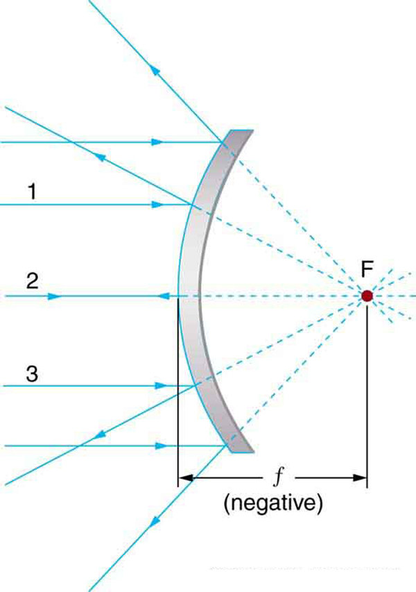
The convex mirror shown in [link] also has a focal point. Parallel rays of light reflected from the mirror seem to originate from the point F at the focal distance behind the mirror. The focal length and power of a convex mirror are negative, since it is a diverging mirror.

Ray tracing is as useful for mirrors as for lenses. The rules for ray tracing for mirrors are based on the illustrations just discussed:
We will use ray tracing to illustrate how images are formed by mirrors, and we can use ray tracing quantitatively to obtain numerical information. But since we assume each mirror is small compared with its radius of curvature, we can use the thin lens equations for mirrors just as we did for lenses.
Consider the situation shown in [link] , concave spherical mirror reflection, in which an object is placed farther from a concave (converging) mirror than its focal length. That is, is positive and > , so that we may expect an image similar to the case 1 real image formed by a converging lens. Ray tracing in [link] shows that the rays from a common point on the object all cross at a point on the same side of the mirror as the object. Thus a real image can be projected onto a screen placed at this location. The image distance is positive, and the image is inverted, so its magnification is negative. This is a case 1 image for mirrors . It differs from the case 1 image for lenses only in that the image is on the same side of the mirror as the object. It is otherwise identical.

Notification Switch
Would you like to follow the 'Physics 101' conversation and receive update notifications?