<< Chapter < Page Chapter >> Page >
  • Explain why a voltmeter must be connected in parallel with the circuit.
  • Draw a diagram showing an ammeter correctly connected in a circuit.
  • Describe how a galvanometer can be used as either a voltmeter or an ammeter.
  • Find the resistance that must be placed in series with a galvanometer to allow it to be used as a voltmeter with a given reading.
  • Explain why measuring the voltage or current in a circuit can never be exact.

Voltmeters measure voltage, whereas ammeters measure current. Some of the meters in automobile dashboards, digital cameras, cell phones, and tuner-amplifiers are voltmeters or ammeters. (See [link] .) The internal construction of the simplest of these meters and how they are connected to the system they monitor give further insight into applications of series and parallel connections.
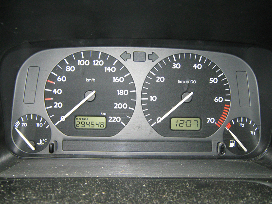
This photograph shows the instruments on a gray Volkswagen Vento dashboard, including the speedometer, odometer, and fuel and temperature gauges, showing some readings.
The fuel and temperature gauges (far right and far left, respectively) in this 1996 Volkswagen are voltmeters that register the voltage output of “sender” units, which are hopefully proportional to the amount of gasoline in the tank and the engine temperature. (credit: Christian Giersing)

Voltmeters are connected in parallel with whatever device’s voltage is to be measured. A parallel connection is used because objects in parallel experience the same potential difference. (See [link] , where the voltmeter is represented by the symbol V.)

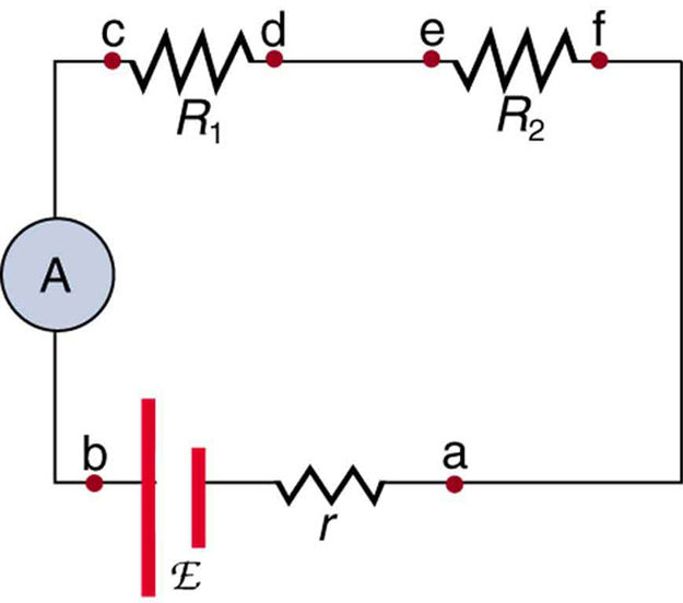
Ammeters are connected in series with whatever device’s current is to be measured. A series connection is used because objects in series have the same current passing through them. (See [link] , where the ammeter is represented by the symbol A.)
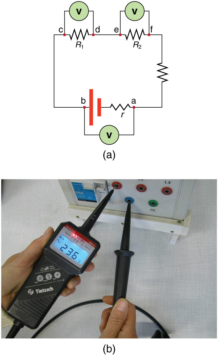
Part a shows a schematic drawing of a circuit with a voltage source and its internal resistance, in series with two load resistors R sub one and R sub two having two probes of a voltmeter connected in parallel with each component. There is another resistor in series to close the circuit. Part b shows a photograph of a black voltmeter connected to two inputs on an electrical device, with a digital readout of the voltage across the source as an L E D display.
(a) To measure potential differences in this series circuit, the voltmeter (V) is placed in parallel with the voltage source or either of the resistors. Note that terminal voltage is measured between points a and b. It is not possible to connect the voltmeter directly across the emf without including its internal resistance, r . (b) A digital voltmeter in use. (credit: Messtechniker, Wikimedia Commons)
The diagram of an electric circuit shows a voltage source of e m f script E and internal resistance r and two resistive loads R sub one and R sub two. All are connected in series with an ammeter A.
An ammeter (A) is placed in series to measure current. All of the current in this circuit flows through the meter. The ammeter would have the same reading if located between points d and e or between points f and a as it does in the position shown. (Note that the script capital E stands for emf, and r stands for the internal resistance of the source of potential difference.)

Analog meters: galvanometers

Analog meters have a needle that swivels to point at numbers on a scale, as opposed to digital meters , which have numerical readouts similar to a hand-held calculator. The heart of most analog meters is a device called a galvanometer    , denoted by G. Current flow through a galvanometer, I G size 12{I rSub { size 8{G} } } {} , produces a proportional needle deflection. (This deflection is due to the force of a magnetic field upon a current-carrying wire.)

The two crucial characteristics of a given galvanometer are its resistance and current sensitivity. Current sensitivity is the current that gives a full-scale deflection    of the galvanometer’s needle, the maximum current that the instrument can measure. For example, a galvanometer with a current sensitivity of 50 μA has a maximum deflection of its needle when 50 μA flows through it, reads half-scale when 25 μA size 12{2"5 "μA} {} flows through it, and so on.

Questions & Answers

what are components of cells
ofosola Reply
twugzfisfjxxkvdsifgfuy7 it
Sami
58214993
Sami
what is a salt
John
the difference between male and female reproduction
John
what is computed
IBRAHIM Reply
what is biology
IBRAHIM
what is the full meaning of biology
IBRAHIM
what is biology
Jeneba
what is cell
Kuot
425844168
Sami
what is cytoplasm
Emmanuel Reply
structure of an animal cell
Arrey Reply
what happens when the eustachian tube is blocked
Puseletso Reply
what's atoms
Achol Reply
discuss how the following factors such as predation risk, competition and habitat structure influence animal's foraging behavior in essay form
Burnet Reply
cell?
Kuot
location of cervical vertebra
KENNEDY Reply
What are acid
Sheriff Reply
define biology infour way
Happiness Reply
What are types of cell
Nansoh Reply
how can I get this book
Gatyin Reply
what is lump
Chineye Reply
what is cell
Maluak Reply
what is biology
Maluak
what is vertibrate
Jeneba
what's cornea?
Majak Reply
what are cell
Achol
Got questions? Join the online conversation and get instant answers!
Jobilize.com Reply
Practice Key Terms 8

Get Jobilize Job Search Mobile App in your pocket Now!

Get it on Google Play Download on the App Store Now


Source:  OpenStax, Physics 101. OpenStax CNX. Jan 07, 2013 Download for free at http://legacy.cnx.org/content/col11479/1.1
Google Play and the Google Play logo are trademarks of Google Inc.

Notification Switch

Would you like to follow the 'Physics 101' conversation and receive update notifications?

Ask