<< Chapter < Page Chapter >> Page >
V = emf Ir = 12.0 V ( 1.188 A ) ( 0.100 Ω ) = 11.9 V.

Discussion for (a)

The terminal voltage here is only slightly lower than the emf, implying that 10 . 0 Ω size 12{"10" "." 0 %OMEGA } {} is a light load for this particular battery.

Solution for (b)

Similarly, with R load = 0 . 500 Ω size 12{R rSub { size 8{"load"} } =0 "." "500"` %OMEGA } {} , the current is

I = emf R load + r = 12 . 0 V 0 . 600 Ω = 20 . 0 A . size 12{I= { {"emf"} over {R rSub { size 8{"load"} } +r} } = { {"12" "." 0" V"} over {0 "." "600 " %OMEGA } } ="20" "." 0" A"} {}

The terminal voltage is now

V = emf Ir = 12.0 V ( 20.0 A ) ( 0.100 Ω ) = 10 . 0 V.

Discussion for (b)

This terminal voltage exhibits a more significant reduction compared with emf, implying 0 . 500 Ω size 12{0 "." "500 " %OMEGA } {} is a heavy load for this battery.

Solution for (c)

The power dissipated by the 0 . 500 - Ω size 12{0 "." "500-" %OMEGA } {} load can be found using the formula P = I 2 R size 12{P=I rSup { size 8{2} } R} {} . Entering the known values gives

P load = I 2 R load = ( 20.0 A ) 2 ( 0 .500 Ω ) = 2.00 × 10 2 W . size 12{P rSub { size 8{"load"} } =I rSup { size 8{2} } R rSub { size 8{"load"} } = \( "400"" A" rSup { size 8{2} } \) \( 0 "." "500" %OMEGA \) ="200"" W"} {}

Discussion for (c)

Note that this power can also be obtained using the expressions V 2 R size 12{ { {V rSup { size 8{2} } } over {R} } } {} or IV size 12{ ital "IV"} {} , where V size 12{V} {} is the terminal voltage (10.0 V in this case).

Solution for (d)

Here the internal resistance has increased, perhaps due to the depletion of the battery, to the point where it is as great as the load resistance. As before, we first find the current by entering the known values into the expression, yielding

I = emf R load + r = 12 . 0 V 1 . 00 Ω = 12 . 0 A . size 12{I= { {"emf"} over {R rSub { size 8{"load"} } +r} } = { {"12" "." 0" V"} over {1 "." "00 " %OMEGA } } ="12" "." 0" A"} {}

Now the terminal voltage is

V = emf Ir = 12.0 V ( 12.0 A ) ( 0.500 Ω ) = 6.00 V,

and the power dissipated by the load is

P load = I 2 R load = ( 12.0 A ) 2 ( 0 . 500 Ω ) = 72 . 0 W . size 12{P rSub { size 8{"load"} } =I rSup { size 8{2} } R rSub { size 8{"load"} } = \( "144"" A" rSup { size 8{2} } \) \( 0 "." "500" %OMEGA \) ="72" "." 0" W"} {}

Discussion for (d)

We see that the increased internal resistance has significantly decreased terminal voltage, current, and power delivered to a load.

Battery testers, such as those in [link] , use small load resistors to intentionally draw current to determine whether the terminal voltage drops below an acceptable level. They really test the internal resistance of the battery. If internal resistance is high, the battery is weak, as evidenced by its low terminal voltage.
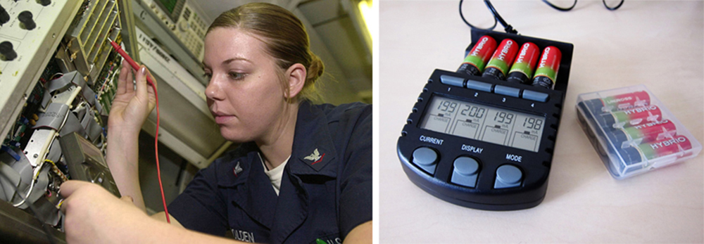
The first photograph shows an avionics electronics technician working inside an aircraft carrier, measuring voltage of a battery with a voltmeter probe. The second photograph shows the small black battery tester which has an LED screen that indicates the terminal voltage of four batteries inserted into its case.
These two battery testers measure terminal voltage under a load to determine the condition of a battery. The large device is being used by a U.S. Navy electronics technician to test large batteries aboard the aircraft carrier USS Nimitz and has a small resistance that can dissipate large amounts of power. (credit: U.S. Navy photo by Photographer’s Mate Airman Jason A. Johnston) The small device is used on small batteries and has a digital display to indicate the acceptability of their terminal voltage. (credit: Keith Williamson)

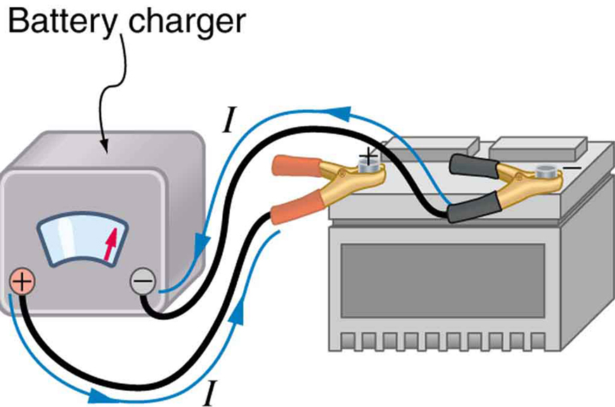
Some batteries can be recharged by passing a current through them in the direction opposite to the current they supply to a resistance. This is done routinely in cars and batteries for small electrical appliances and electronic devices, and is represented pictorially in [link] . The voltage output of the battery charger must be greater than the emf of the battery to reverse current through it. This will cause the terminal voltage of the battery to be greater than the emf, since V = emf Ir size 12{V="emf" - ital "Ir"} {} , and I size 12{I} {} is now negative.

The diagram shows a car battery being charged with cables from a battery charger. The current flows from the positive terminal of the charger to the positive terminal of the battery, through the battery and back out the negative terminal of the battery to the negative terminal of the charger.
A car battery charger reverses the normal direction of current through a battery, reversing its chemical reaction and replenishing its chemical potential.

Multiple voltage sources

There are two voltage sources when a battery charger is used. Voltage sources connected in series are relatively simple. When voltage sources are in series, their internal resistances add and their emfs add algebraically. (See [link] .) Series connections of voltage sources are common—for example, in flashlights, toys, and other appliances. Usually, the cells are in series in order to produce a larger total emf.

Practice Key Terms 4

Get Jobilize Job Search Mobile App in your pocket Now!

Get it on Google Play Download on the App Store Now


Source:  OpenStax, Physics 101. OpenStax CNX. Jan 07, 2013 Download for free at http://legacy.cnx.org/content/col11479/1.1
Google Play and the Google Play logo are trademarks of Google Inc.

Notification Switch

Would you like to follow the 'Physics 101' conversation and receive update notifications?

Ask