| << Chapter < Page | Chapter >> Page > |
Note that if is positive, then is positive, meaning that work is done by the gas on the outside world.
(Note that the pressure involved in this work that we’ve called is the pressure of the gas inside the tank. If we call the pressure outside the tank , an expanding gas would be working against the external pressure; the work done would therefore be (isobaric process). Many texts use this definition of work, and not the definition based on internal pressure, as the basis of the First Law of Thermodynamics. This definition reverses the sign conventions for work, and results in a statement of the first law that becomes .)
It is not surprising that , since we have already noted in our treatment of fluids that pressure is a type of potential energy per unit volume and that pressure in fact has units of energy divided by volume. We also noted in our discussion of the ideal gas law that has units of energy. In this case, some of the energy associated with pressure becomes work.
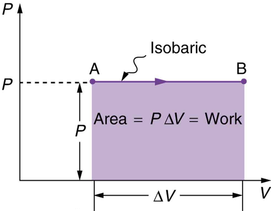
[link] shows a graph of pressure versus volume (that is, a diagram for an isobaric process. You can see in the figure that the work done is the area under the graph. This property of diagrams is very useful and broadly applicable: the work done on or by a system in going from one state to another equals the area under the curve on a diagram .


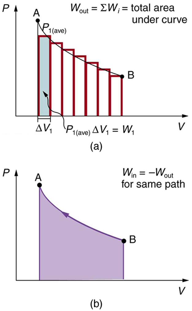
We can see where this leads by considering [link] (a), which shows a more general process in which both pressure and volume change. The area under the curve is closely approximated by dividing it into strips, each having an average constant pressure . The work done is for each strip, and the total work done is the sum of the . Thus the total work done is the total area under the curve. If the path is reversed, as in [link] (b), then work is done on the system. The area under the curve in that case is negative, because is negative.
diagrams clearly illustrate that the work done depends on the path taken and not just the endpoints . This path dependence is seen in [link] (a), where more work is done in going from A to C by the path via point B than by the path via point D. The vertical paths, where volume is constant, are called isochoric processes. Since volume is constant, , and no work is done in an isochoric process. Now, if the system follows the cyclical path ABCDA, as in [link] (b), then the total work done is the area inside the loop. The negative area below path CD subtracts, leaving only the area inside the rectangle. In fact, the work done in any cyclical process (one that returns to its starting point) is the area inside the loop it forms on a diagram, as [link] (c) illustrates for a general cyclical process. Note that the loop must be traversed in the clockwise direction for work to be positive—that is, for there to be a net work output.

Notification Switch
Would you like to follow the 'College physics: physics of california' conversation and receive update notifications?