| << Chapter < Page | Chapter >> Page > |
To begin understanding how to decode the Dolby Pro Logic Surround Sound standard, you will implement a Pro Logicencoder and a passive surround sound decoder. This decoder operates on many of the same principles as the moresophisticated commercial systems. Significantly more technical information regarding Dolby Pro Logic can be foundat Gundry .
You will create a MATLAB implementation of the passive encoder given by the block diagram in [link] .

The encoder block diagram shows four input signals: Left,
Center, Right, and Surround. These are audio signals createdby a sound designer during movie production that are intended
to play back from speakers positioned at the left side, at thefront-center, at the right side, and at the rear of a home
theater. The system in the block diagram encodes these fourchannels of audio on two output channels,
Lt and
Rt , in such a way that an appropriately designed
decoder can approximately recover the original four channels.Additionally, to accommodate those who do not use a surround
sound receiver, the encoder outputs are listenable when playedback on a stereo (two-channel) system, even retaining the
correct left-right balance.
The basic components of the encoder are multipliers, adders, a Hilbert transform, a band-pass filter, and a Dolby NoiseReduction encoder. If you wish to implement Dolby Noise Reduction, refer to Dressler . The other components are discussed below.
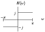
The transfer function of the Hilbert Transform is shown in
[link] . The Hilbert Transform is an ideal
(unrealizable) all-pass filter with a phase shift of
. Observe that a cosine input becomes a sine and a
sine input becomes a negative cosine. In MATLAB, generate acosine and sine signal of some frequency and use the
hilbert function to perform on each signal an
approximation to the Hilbert Transform. (Why is the HilbertTransform unrealizable?) The imaginary part of the Hilbert
Transform output (
imag(hilbert(signal)) ) will be the
phase-shifted version of the original signal. Plot
each signal to confirm your expectations.

For the band-pass filter, design a second-order Butterworth
filter using the
butter function in MATLAB.
Create four channels of audio to encode as a Pro Logic
Surround Signal. Use simple mixing techniques to generatethe four channels. For example, use a voice signal for the
center channel and fade a roaming sound such as a helicopterfrom left to right and front to back. In MATLAB, use the
wavread and
auread functions to
read
.wav and
.au audio files
which can be found on the Internet.
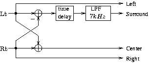
Implement the passive decoder shown in [link] on the DSP. Use an appropriate time delay based on the distance between the front and back speakers and the speed ofsound.

Is there significant crosstalk between the front and surround speakers? Do you get good separation between left and rightspeakers? Can you explain how the decoder recovers approximations to the original four channels?
Differences in power levels between channels are used to enhance the directional effect in what is called "activedecoding." One way to find the power level in a signal is to square it and pass the squared signal through a verynarrow-band low-pass filter ( ). How is the low-frequency content of the squared signal related to the power of the original signal? Rememberthat squaring a signal in the time domain is equivalent to convolving the signal with itself in the frequency domain.
To implement a very narrow-band low-pass filter, you may consider using the Chamberlin filter topology, described in Surround Sound: Chamberlin Filters .

Notification Switch
Would you like to follow the 'Digital signal processing laboratory (ece 420)' conversation and receive update notifications?