<< Chapter < Page Chapter >> Page >
  • Calculate the flux of a uniform magnetic field through a loop of arbitrary orientation.
  • Describe methods to produce an electromotive force (emf) with a magnetic field or magnet and a loop of wire.

The apparatus used by Faraday to demonstrate that magnetic fields can create currents is illustrated in [link] . When the switch is closed, a magnetic field is produced in the coil on the top part of the iron ring and transmitted to the coil on the bottom part of the ring. The galvanometer is used to detect any current induced in the coil on the bottom. It was found that each time the switch is closed, the galvanometer detects a current in one direction in the coil on the bottom. (You can also observe this in a physics lab.) Each time the switch is opened, the galvanometer detects a current in the opposite direction. Interestingly, if the switch remains closed or open for any length of time, there is no current through the galvanometer. Closing and opening the switch induces the current. It is the change in magnetic field that creates the current. More basic than the current that flows is the emf that causes it. The current is a result of an emf induced by a changing magnetic field , whether or not there is a path for current to flow.
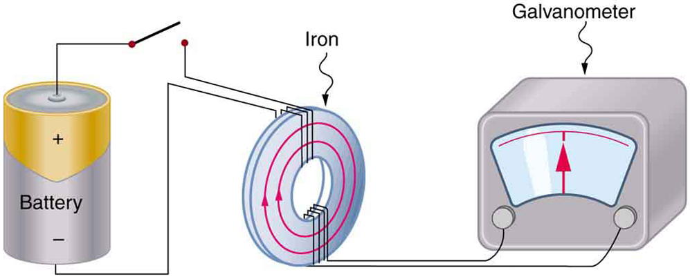
The picture shows Faraday’s apparatus for demonstrating that a magnetic field can produce a current. It consists of a cylinder shaped battery. The positive end of the battery is connected to an open switch. There is a ring shaped iron core consisting of a set of coils one on the top and another at the bottom. The other end of the switch is connected to one end of the top coil. The other end of the top coil is connected back to the battery. Both the ends of the bottom coil are shown connected across a galvanometer box which shows a null deflection.
Faraday’s apparatus for demonstrating that a magnetic field can produce a current. A change in the field produced by the top coil induces an emf and, hence, a current in the bottom coil. When the switch is opened and closed, the galvanometer registers currents in opposite directions. No current flows through the galvanometer when the switch remains closed or open.

An experiment easily performed and often done in physics labs is illustrated in [link] . An emf is induced in the coil when a bar magnet is pushed in and out of it. Emfs of opposite signs are produced by motion in opposite directions, and the emfs are also reversed by reversing poles. The same results are produced if the coil is moved rather than the magnet—it is the relative motion that is important. The faster the motion, the greater the emf, and there is no emf when the magnet is stationary relative to the coil.
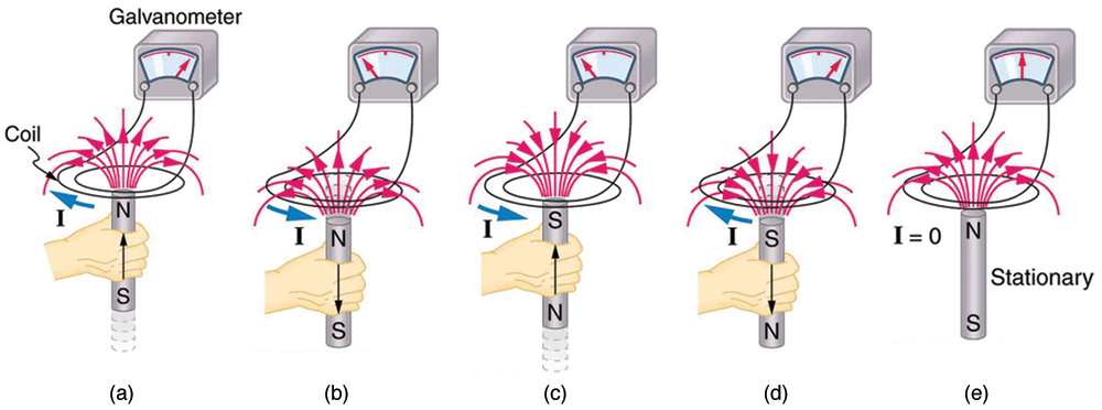
The diagram shows five stages of an experiment done by moving a magnet relative to a coil and measuring the e m f produced. The first stage of the experiment shows a wire coil with two loops connected across a galvanometer. The loop is in horizontal plane. A cylindrical rod shaped magnet is moved upward through the loop with the north pole of the magnet facing the loop and the South Pole away from the loop. The magnetic lines of force of the magnet are shown to emerge out from the North Pole and intersect the coil. A current is shown to be induced in the coil in clockwise direction. The galvanometer needle is shown to deflect toward right. The second stage of the experiment shows the next state of the first stage of the experiment. The cylindrical rod shaped magnet is now moved downward away from the loop with the north pole of the magnet facing the loop and South Pole away from the loop. The magnetic lines of force of the magnet are shown to emerge out from the North Pole and intersect the coil. A current is shown to be induced in the coil in anti clockwise direction. The galvanometer needle is shown to deflect toward left. The third stage of the experiment shows a wire coil with two loops connected across a galvanometer. The loop is in horizontal plane. A cylindrical rod shaped magnet is moved upward through the loop with the south pole of the magnet facing the loop and the North Pole away from the loop. The magnetic lines of force of the magnet are shown to merge into the South Pole and intersect the coil. A current is shown to be induced in the coil in anti clockwise direction. The galvanometer needle is shown to deflect toward left. The fourth stage of the experiment shows the next state of the third stage of the experiment. The cylindrical rod shaped magnet is now moved downward away from the loop with the south pole of the magnet facing the loop and the North Pole away from the loop. The magnetic lines of force of the magnet are shown to merge into the South Pole and intersect the coil. A current is shown to be induced in the coil in clockwise direction. The galvanometer needle is shown to deflect toward right. The fifth stage of the experiment shows a wire coil with two loops connected across a galvanometer. The loop is in horizontal plane. A cylindrical rod shaped magnet is held stationary near the loop with the north pole of the magnet facing the loop and south away from the loop. The magnetic lines of force of the magnet are shown to emerge out from the North Pole and intersect the coil. No current is induced in the coil. The galvanometer needle does not deflect.
Movement of a magnet relative to a coil produces emfs as shown. The same emfs are produced if the coil is moved relative to the magnet. The greater the speed, the greater the magnitude of the emf, and the emf is zero when there is no motion.

The method of inducing an emf used in most electric generators is shown in [link] . A coil is rotated in a magnetic field, producing an alternating current emf, which depends on rotation rate and other factors that will be explored in later sections. Note that the generator is remarkably similar in construction to a motor (another symmetry).
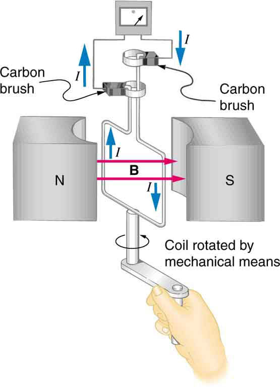
The figure shows a schematic diagram of an electric generator. It consists of a rotating rectangular coil placed between the two poles of a permanent magnet shown as two rectangular blocks curved on side facing the coil. The magnetic field B is shown pointing from the North to the South Pole. The two ends of this coil are connected to the two small rings. The two conducting carbon brushes are kept pressed separately on both the rings. The coil is attached to an axle with a handle at the other end. The axle may be mechanically rotated from outside to rotate the coil inside the magnetic field. Outer ends of the two brushes are connected to the galvanometer. A current is shown to flow in the coil in anti clockwise direction and the galvanometer shows a deflection.
Rotation of a coil in a magnetic field produces an emf. This is the basic construction of a generator, where work done to turn the coil is converted to electric energy. Note the generator is very similar in construction to a motor.

So we see that changing the magnitude or direction of a magnetic field produces an emf. Experiments revealed that there is a crucial quantity called the magnetic flux    , Φ size 12{Φ} {} , given by

Φ = BA cos θ , size 12{Φ= ital "BA""cos"θ} {}

where B size 12{B} {} is the magnetic field strength over an area A size 12{A} {} , at an angle θ with the perpendicular to the area as shown in [link] . Any change in magnetic flux Φ size 12{Φ} {} induces an emf. This process is defined to be electromagnetic induction    . Units of magnetic flux Φ size 12{Φ} {} are T m 2 size 12{T cdot m rSup { size 8{2} } } {} . As seen in [link] , B cos θ = B size 12{B"cos"θ=B rSub { size 8{ ortho } } } {} , which is the component of B size 12{B} {} perpendicular to the area A size 12{A} {} . Thus magnetic flux is Φ = B A size 12{Φ=B rSub { size 8{ ortho } } A} {} , the product of the area and the component of the magnetic field perpendicular to it.
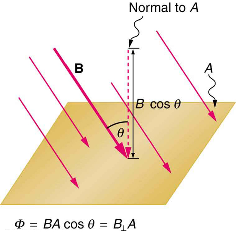
Figure shows a flat square shaped surface A. The magnetic field B is shown to act on the surface at an angle theta with the normal to the surface A. The cosine component of magnetic field B cos theta is shown to act parallel to the normal to the surface.
Magnetic flux Φ size 12{Φ} {} is related to the magnetic field and the area over which it exists. The flux Φ = BA cos θ size 12{Φ= ital "BA""cos"θ} {} is related to induction; any change in Φ size 12{Φ} {} induces an emf.

All induction, including the examples given so far, arises from some change in magnetic flux Φ size 12{Φ} {} . For example, Faraday changed B size 12{B} {} and hence Φ size 12{Φ} {} when opening and closing the switch in his apparatus (shown in [link] ). This is also true for the bar magnet and coil shown in [link] . When rotating the coil of a generator, the angle θ size 12{θ} {} and, hence, Φ size 12{Φ} {} is changed. Just how great an emf and what direction it takes depend on the change in Φ size 12{Φ} {} and how rapidly the change is made, as examined in the next section.

Section summary

  • The crucial quantity in induction is magnetic flux Φ size 12{Φ} {} , defined to be Φ = BA cos θ size 12{Φ= ital "BA""cos"θ} {} , where B size 12{B} {} is the magnetic field strength over an area A size 12{A} {} at an angle θ size 12{θ} {} with the perpendicular to the area.
  • Units of magnetic flux Φ size 12{Φ} {} are T m 2 size 12{T cdot m rSup { size 8{2} } } {} .
  • Any change in magnetic flux Φ size 12{Φ} {} induces an emf—the process is defined to be electromagnetic induction.

Conceptual questions

How do the multiple-loop coils and iron ring in the version of Faraday’s apparatus shown in [link] enhance the observation of induced emf?

When a magnet is thrust into a coil as in [link] (a), what is the direction of the force exerted by the coil on the magnet? Draw a diagram showing the direction of the current induced in the coil and the magnetic field it produces, to justify your response. How does the magnitude of the force depend on the resistance of the galvanometer?

Explain how magnetic flux can be zero when the magnetic field is not zero.

Is an emf induced in the coil in [link] when it is stretched? If so, state why and give the direction of the induced current.

The first part of the figure shows a circular coil of wire held in a magnetic field. The magnetic field points into the paper. The coil is held using both the hands to stretch it. The second part of the figure shows the same circular coil of wire stretched in the magnetic field.
A circular coil of wire is stretched in a magnetic field.

Problems&Exercises

What is the value of the magnetic flux at coil 2 in [link] due to coil 1?
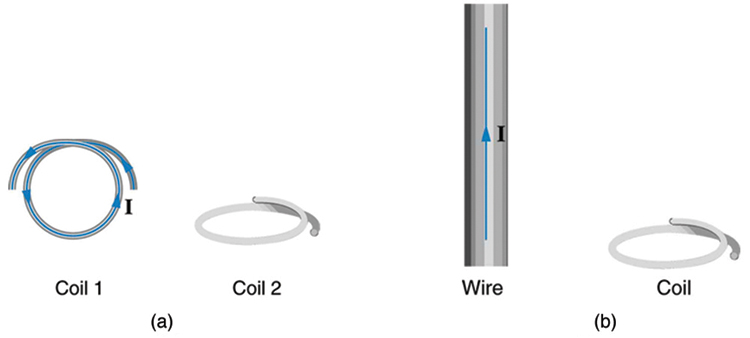
The first part of the figure shows two single loop coils. The coil one is held vertical with a current shown to flow in anti clockwise direction. The second coil, coil two is held horizontal. The two coils are shown to be held perpendicular to each other. The second image shows a wire held vertical carrying a current in upward direction. There is a single loop coil next to the wire held horizontal.
(a) The planes of the two coils are perpendicular. (b) The wire is perpendicular to the plane of the coil.

Zero

What is the value of the magnetic flux through the coil in [link] (b) due to the wire?

Questions & Answers

it is the relatively stable flow of income
Chidubem Reply
what is circular flow of income
Divine Reply
branches of macroeconomics
SHEDRACK Reply
what is Flexible exchang rate?
poudel Reply
is gdp a reliable measurement of wealth
Atega Reply
introduction to econometrics
Husseini Reply
Hi
mostafa
hi
LEMLEM
hello
Sammol
hi
Mahesh
bi
Ruqayat
hi
Ruqayat
Hi fellas
Nyawa
hey
Sammol
hi
God
hello
Jahara
Good morning
Jorge
hi
abubakar
hi
Nmesoma
hi
Mahesh
Hi
Tom
Why is unemployment rate never zero at full employment?
Priyanka Reply
bcoz of existence of frictional unemployment in our economy.
Umashankar
what is flexible exchang rate?
poudel
due to existence of the pple with disabilities
Abdulraufu
the demand of a good rises, causing the demand for another good to fall
Rushawn Reply
is it possible to leave every good at the same level
Joseph
I don't think so. because check it, if the demand for chicken increases, people will no longer consume fish like they used to causing a fall in the demand for fish
Anuolu
is not really possible to let the value of a goods to be same at the same time.....
Salome
Suppose the inflation rate is 6%, does it mean that all the goods you purchase will cost 6% more than previous year? Provide with reasoning.
Geetha Reply
Not necessarily. To measure the inflation rate economists normally use an averaged price index of a basket of certain goods. So if you purchase goods included in the basket, you will notice that you pay 6% more, otherwise not necessarily.
Waeth
discus major problems of macroeconomics
Alii Reply
what is the problem of macroeconomics
Yoal
Economic growth Stable prices and low unemployment
Ephraim
explain inflationcause and itis degre
Miresa Reply
what is inflation
Getu
increase in general price levels
WEETO
Good day How do I calculate this question: C= 100+5yd G= 2000 T= 2000 I(planned)=200. Suppose the actual output is 3000. What is the level of planned expenditures at this level of output?
Chisomo Reply
how to calculate actual output?
Chisomo
how to calculate the equilibrium income
Beshir
Criteria for determining money supply
Thapase Reply
who we can define macroeconomics in one line
Muhammad
Aggregate demand
Mohammed
C=k100 +9y and i=k50.calculate the equilibrium level of output
Mercy Reply
Hi
Isiaka
Hi
Geli
hy
Man
👋
Bahunda
hy how are you?
Man
ys
Amisha
how are you guys
Sekou
f9 guys
Amisha
how are you guys
Sekou
ys am also fine
Amisha
fine and you guys
Geli
from Nepal
Amisha
nawalparasi district from belatari
Amisha
nd u
Amisha
I am Camara from Guinea west Africa... happy to meet you guys here
Sekou
ma management ho
Amisha
ahile becheclor ho
Amisha
hjr ktm bta ho ani k kaam grnu hunxa tw
Amisha
belatari
Amisha
1st year ho
Amisha
nd u
Amisha
ahh
Amisha
kaha biratnagar
Amisha
ys
Amisha
kina k vo
Amisha
money as unit of account means what?
Kalombe
A unit of account is something that can be used to value goods and services and make calculations
Jim
all of you please speak in English I can't understand you're language
Muhammad
I want to know how can we define macroeconomics in one line
Muhammad
it must be .9 or 0.9 no Mpc is greater than 1 Y=100+.9Y+50 Y-.9Y=150 0.1Y/0.1=150/0.1 Y=1500
Kalombe
Mercy is it clear?😋
Kalombe
hi can someone help me on this question If a negative shocks shifts the IS curve to the left, what type of policy do you suggest so as to stabilize the level of output? discuss your answer using appropriate graph.
Galge Reply
if interest rate is increased this will will reduce the level of income shifting the curve to the left ◀️
Kalombe
Got questions? Join the online conversation and get instant answers!
Jobilize.com Reply
Practice Key Terms 2

Get Jobilize Job Search Mobile App in your pocket Now!

Get it on Google Play Download on the App Store Now


Source:  OpenStax, College physics (engineering physics 2, tuas). OpenStax CNX. May 08, 2014 Download for free at http://legacy.cnx.org/content/col11649/1.2
Google Play and the Google Play logo are trademarks of Google Inc.

Notification Switch

Would you like to follow the 'College physics (engineering physics 2, tuas)' conversation and receive update notifications?

Ask