| << Chapter < Page | Chapter >> Page > |
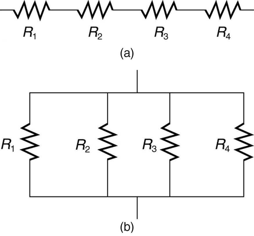
Most circuits have more than one component, called a resistor that limits the flow of charge in the circuit. A measure of this limit on charge flow is called resistance . The simplest combinations of resistors are the series and parallel connections illustrated in [link] . The total resistance of a combination of resistors depends on both their individual values and how they are connected.

When are resistors in series ? Resistors are in series whenever the flow of charge, called the current , must flow through devices sequentially. For example, if current flows through a person holding a screwdriver and into the Earth, then in [link] (a) could be the resistance of the screwdriver’s shaft, the resistance of its handle, the person’s body resistance, and the resistance of her shoes.
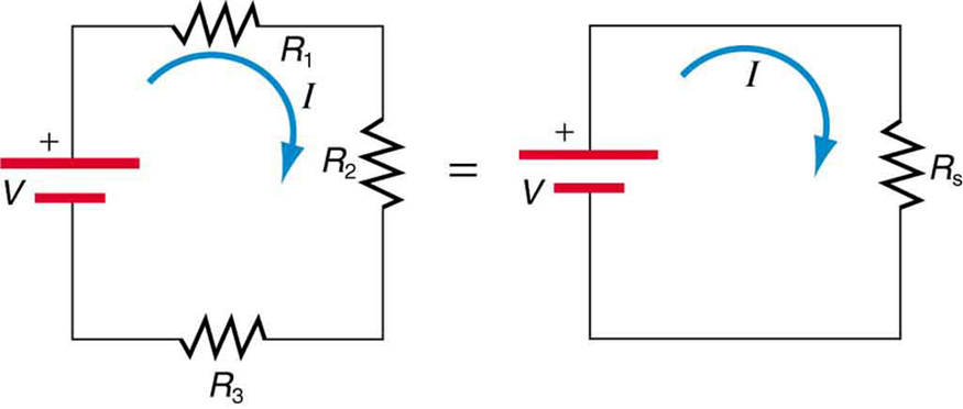
[link] shows resistors in series connected to a voltage source. It seems reasonable that the total resistance is the sum of the individual resistances, considering that the current has to pass through each resistor in sequence. (This fact would be an advantage to a person wishing to avoid an electrical shock, who could reduce the current by wearing high-resistance rubber-soled shoes. It could be a disadvantage if one of the resistances were a faulty high-resistance cord to an appliance that would reduce the operating current.)

To verify that resistances in series do indeed add, let us consider the loss of electrical power, called a voltage drop , in each resistor in [link] .
According to Ohm’s law , the voltage drop, , across a resistor when a current flows through it is calculated using the equation , where equals the current in amps (A) and is the resistance in ohms . Another way to think of this is that is the voltage necessary to make a current flow through a resistance .
So the voltage drop across is , that across is , and that across is . The sum of these voltages equals the voltage output of the source; that is,
This equation is based on the conservation of energy and conservation of charge. Electrical potential energy can be described by the equation , where is the electric charge and is the voltage. Thus the energy supplied by the source is , while that dissipated by the resistors is
The derivations of the expressions for series and parallel resistance are based on the laws of conservation of energy and conservation of charge, which state that total charge and total energy are constant in any process. These two laws are directly involved in all electrical phenomena and will be invoked repeatedly to explain both specific effects and the general behavior of electricity.

Notification Switch
Would you like to follow the 'Abe advanced level physics' conversation and receive update notifications?