| << Chapter < Page | Chapter >> Page > |
This practical guide leads the reader through solving the problem from start to finish. You will learn to: define a problem clearly,organize your problem solving project, analyze the problem to identify the root causes, solve the problem by taking corrective action, andprove the problem is really solved by measuring the results.
—Jeanne Sawyer, When Stuff Happens: A Practical Guide to Solving Problems Permanently , Sawyer Publishing Group, 2001
There is nothing new in this chapter. Really. By peeling away the outer, most accessible layers of thecommunication system, the previous chapters have provided all of the piecesneeded to build an idealized digital communication system, and this chapter just shows how to combine the piecesinto a functioning system. Then we get to play with the system a bit, asking a series of “what if” questions.
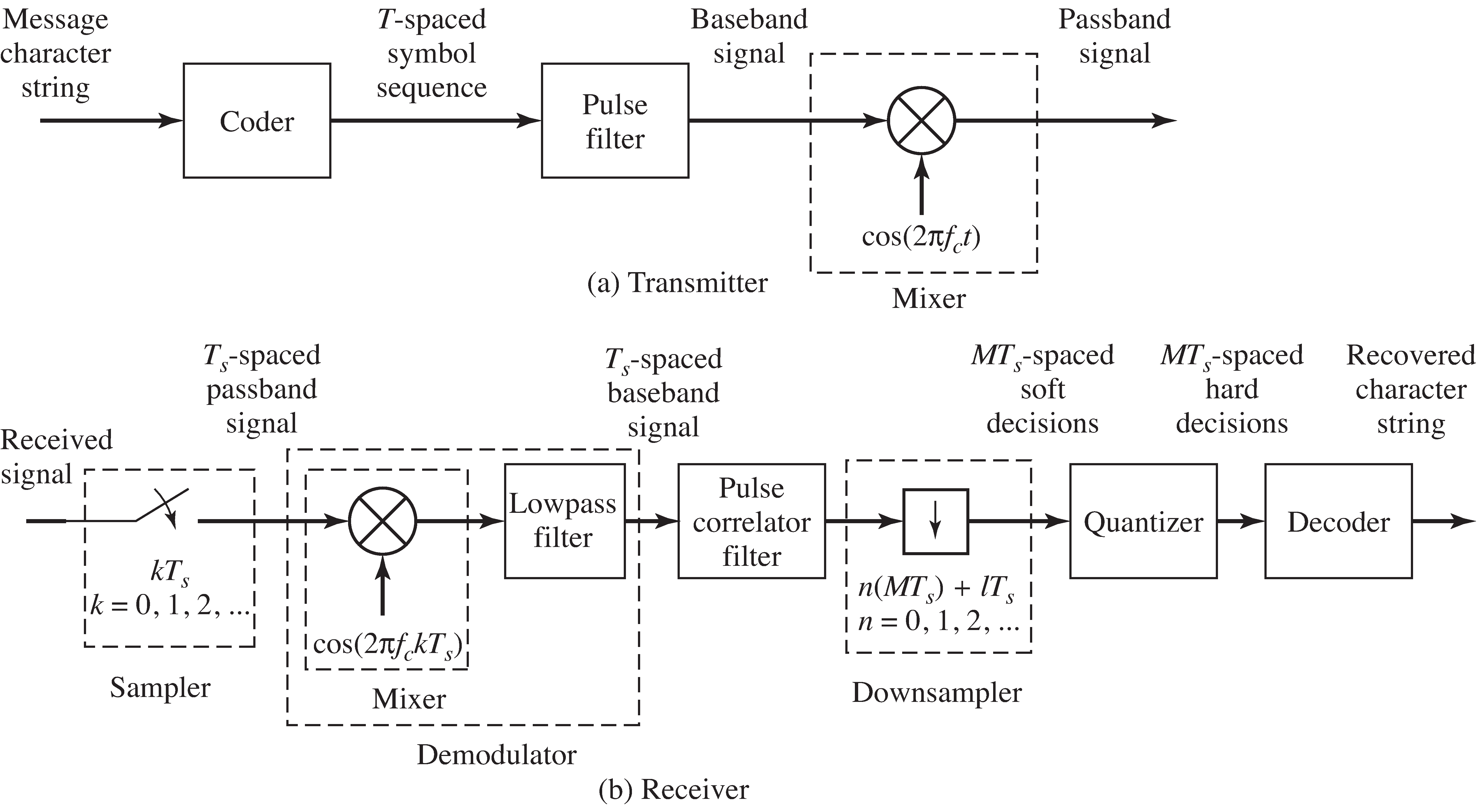
In outline, the idealized system consists of two parts, rather than three, since the channel is assumed to be noiseless anddisturbance free.
The Transmitter
The Digital Receiver
Each of these procedures is familiar from earlier chapters, and you may have already written M atlab code to perform them. It is time to combine the elements into a full simulation ofa transmitter and receiver pair that can function successfully in an ideal setting.
The system is illustrated in the block diagram of [link] . This system is described in great detail in "Simulating the Ideal System" , which also provides a M atlab version of the transmitter and receiver. Once everything is pieced together, it is easy toverify that messages can be sent reliably from transmitter to receiver.
Unfortunately, some of the assumptions made in the ideal setting are unlikely to hold in practice;for example, the presumption that there is no interference from other transmitters, that there is no noise,that the gain of the channel is always unity, that the signal leaving the transmitteris exactly the same as the signal at the input to the digital receiver. All of these assumptions will almost certainly be violated in practice.Stuff happens!

"Flat Fading: A Simple Impairment and a Simple Fix" begins to accommodate some of the nonidealities encountered in real systems byaddressing the possibility that the channel gain might vary with time.For example, a large metal truck might abruptly move between a cell phone and the antenna at the base station,causing the channel gain to drop precipitously. If the receiver cannot react to such achange, it may suffer debilitating errors when reconstructing the message. "Flat Fading: A Simple Impairment and a Simple Fix" examines the effectiveness of incorporating an automatic gain control (AGC) adaptive element(as described in [link] ) at the front-end of the receiver.With care, the AGC can accommodate the varying gain. The success of the AGC is encouraging.Perhaps there are simple ways to compensate for other common impairments.

Notification Switch
Would you like to follow the 'Software receiver design' conversation and receive update notifications?