<< Chapter < Page Chapter >> Page >

Production of real-valued outputs

It is frequently the case that the best system-wide choice is the use of a transmultiplexer producing complex-valued outputs even though some of the system outputs need to be real-valued. An example of this is when a transmultiplexer is used to supply all transmuxed signals to an analyzer of some sort, plus a few selected signals for a downstream processor or transmission system. If the analysis processing is best done with complex-valued data (and it often is), then the best system-level choice is often to use a complex-output transmux and then to convert the relatively few system outputs to a real-valued representation. This appendix describes how this can be done.

Producing a real-valued signal from a complex-valued one is as simple as taking its real part, but for this to be valid, the complex-valued signal must be sampled frequently enough. In actual practice, this condition is not usually met and it is necessary to increase the complex-valued signal's sampling rate by a factor of two before extracting the real part. Another complication is that the user may desire to choose the spectral orientation of the resulting real-valued signal.

[link] shows the spectral implications of the steps usually taken to interpolate the complex-valued signal, specify its sideband orientation, and produce a real-valued representation.

[link] (a) shows the assumed spectrum of the complex-valued input signal z ( r ) . The signal z ( r ) is assumed to be the output of a complex-valued FDM-TDM transmultiplexer. It is sampled at the rate f and is spectrally oriented so that an increasing input frequency results in a higher output frequency. We'll term this upper sideband . Note that the bandwidth of z ( r ) is less than f .

We now upconvert z ( r ) by f 2 Hz by multiplying it by ( - 1 ) r . This is shown in [link] (b). The signal is now centered around f 2 instead of 0 Hz. The sampling rate is doubled by zero-filling z ¯ ( r ) , that is, z ¯ ( k ) is created by setting z ¯ ( k = 2 r ) = z ( r ) ( - l ) r for even values of k and z ¯ ( k ) = 0 for odd values of k . The spectral effects of this zero-filling are shown in [link] (c). The sampling rate is now 2 f and two upper sideband images of the original signal are present, one centered at f 2 and the other at - f 2 .

The next step is to bandpass filter the desired image. Two filter transfer functions are shown in [link] (d). We focus first on the one drawn with the solid line for now. When the zero-filled input signal Z ¯ ( k ) is convolved with the filter having this response, the higher of the two images is preserved and the lower one suppressed. This is shown in [link] (e).
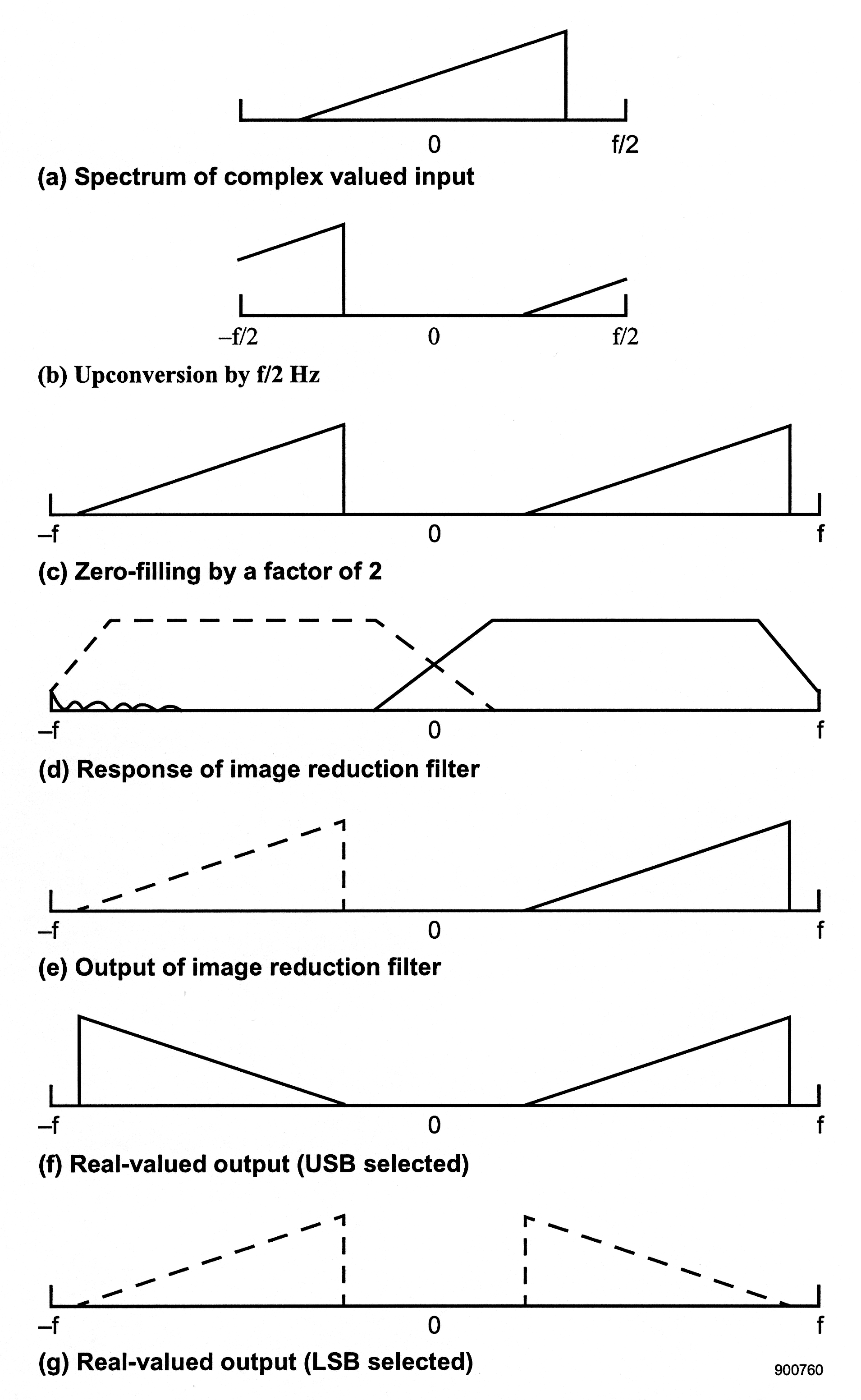
This figure consist of 7 images arranged vertically. The top one is labeled (a) Spectrum of Complex valued input, and it consists of a horizontal line with the left extreme labeleed f/2 and the middle labeled 0. On this line there is a single right triangle. The second image is labeled (b) Upconversion by f/2Hz. The image consist of a horizontal line with the extremes labeled -f/2 on the left and f/2 on the left and the middle labeled 0. On this line on the far left is a right portion of a right triangle which is comprised of the right angle formed with bottom horizontal line and a portion on the hypotenuese while on the right side is the left most portion of a right triangle. The third image is labeled (c) zero-filling by a factor of 2 and it consist of a long horizontal line with the extremes labeled -f on the left, o in the middle and f on the right. On this line there are two right triangles, one on the left and one on the right. The fourth image is labeled (d) response of image reduction filter. It consist of a horizontal line labeled -f on the left, 0 in the middle, and f on the right. On this line the are two trapazoid-esque figures. On the left is a trapazoid figure that is formed by dashed lines. The top and the bottom horizontal lines are parallel while the left adn right lines of the trapazoid angle to the right and left respectively. The bottom line of this trapazoid is squiggly on the left most portion. The right trapazoid is formed by solid lines. The top line and bottom horizontal line are parallel and the sides angle in toward each other the far left line of this trapazoid and the far right line of the other trapazoid cross and form a triangle at the center near the the label 0. The fifth image is labeled (d) Output of image reduction filter. This image is exactly like the third image except that the left right triangle is formed by dashed lines. The sixth image is labeled (f) Real-valued output (USB selected) and it consist of a horizontal line with the extremes labeled -f on the left and f on the right and 0 in the middle. On the left is a right triangle with the right angle on its bottom left. On the right side of the line is a right triangle with its right angle on the bottom right. The seventh image is labeled (g) real-valued output (LSB selected) and it consist of a horizontal line with its extremes labeled -f on the left and f on the right with 0 in the middle. On the far left of this line there is a right triangle formed by dashed lines with its right angle on its bottom right. On the far left of this line there is another right triangle formed by dashed lines with its right angle on its bottom left.
Spectral Implication of Each Step of the Sample-Rate Doubling Used to Produce Real-Valued Outputs

Obviously, the use of a filter with transmission characteristics shown in the dashed lines in [link] (d) would have the effect of selecting the other image, the one shown in dashed lines in [link] (e).

As a result of the filtering, only one image remains and which image it is depends on the bandpass filter chosen. The last step is the production of the real-valued output by simply taking the real part of the complex-valued signal that appears at the filter's output. Since real-valued signals must have spectral symmetry about the origin, this extraction of the real part has the effect of producing an another image of the input, only this one has the opposite sideband orientation. If the upper image is selected by the bandpass filter, then spectrum of the output signal is as shown in [link] (f). We term this as upper sideband since the positive frequency image has the same orientation as the original complex-valued input signal. Choosing the lower image with the bandpass filter has the effect of producing the spectral relationship shown in [link] (g), the so-called lower sideband or inverted case .

Questions & Answers

what is defense mechanism
Chinaza Reply
what is defense mechanisms
Chinaza
I'm interested in biological psychology and cognitive psychology
Tanya Reply
what does preconceived mean
sammie Reply
physiological Psychology
Nwosu Reply
How can I develope my cognitive domain
Amanyire Reply
why is communication effective
Dakolo Reply
Communication is effective because it allows individuals to share ideas, thoughts, and information with others.
effective communication can lead to improved outcomes in various settings, including personal relationships, business environments, and educational settings. By communicating effectively, individuals can negotiate effectively, solve problems collaboratively, and work towards common goals.
it starts up serve and return practice/assessments.it helps find voice talking therapy also assessments through relaxed conversation.
miss
Every time someone flushes a toilet in the apartment building, the person begins to jumb back automatically after hearing the flush, before the water temperature changes. Identify the types of learning, if it is classical conditioning identify the NS, UCS, CS and CR. If it is operant conditioning, identify the type of consequence positive reinforcement, negative reinforcement or punishment
Wekolamo Reply
please i need answer
Wekolamo
because it helps many people around the world to understand how to interact with other people and understand them well, for example at work (job).
Manix Reply
Agreed 👍 There are many parts of our brains and behaviors, we really need to get to know. Blessings for everyone and happy Sunday!
ARC
A child is a member of community not society elucidate ?
JESSY Reply
Isn't practices worldwide, be it psychology, be it science. isn't much just a false belief of control over something the mind cannot truly comprehend?
Simon Reply
compare and contrast skinner's perspective on personality development on freud
namakula Reply
Skinner skipped the whole unconscious phenomenon and rather emphasized on classical conditioning
war
explain how nature and nurture affect the development and later the productivity of an individual.
Amesalu Reply
nature is an hereditary factor while nurture is an environmental factor which constitute an individual personality. so if an individual's parent has a deviant behavior and was also brought up in an deviant environment, observation of the behavior and the inborn trait we make the individual deviant.
Samuel
I am taking this course because I am hoping that I could somehow learn more about my chosen field of interest and due to the fact that being a PsyD really ignites my passion as an individual the more I hope to learn about developing and literally explore the complexity of my critical thinking skills
Zyryn Reply
good👍
Jonathan
and having a good philosophy of the world is like a sandwich and a peanut butter 👍
Jonathan
generally amnesi how long yrs memory loss
Kelu Reply
interpersonal relationships
Abdulfatai Reply
Got questions? Join the online conversation and get instant answers!
Jobilize.com Reply

Get Jobilize Job Search Mobile App in your pocket Now!

Get it on Google Play Download on the App Store Now


Source:  OpenStax, An introduction to the fdm-tdm digital transmultiplexer. OpenStax CNX. Nov 16, 2010 Download for free at http://cnx.org/content/col11165/1.2
Google Play and the Google Play logo are trademarks of Google Inc.

Notification Switch

Would you like to follow the 'An introduction to the fdm-tdm digital transmultiplexer' conversation and receive update notifications?

Ask