| << Chapter < Page | Chapter >> Page > |
(If you are able to use the svg file mentioned below to create tactile graphics, it probably won't be necessary for you to do the graph-board exercise. You can explore the tactile graphics instead.)
The vertices of a right triangle
Each pushpin represents a vertex of a right triangle. If you enclose all three pushpins with a rubber band, you will have "drawn" a right triangle withits base on the horizontal axis.
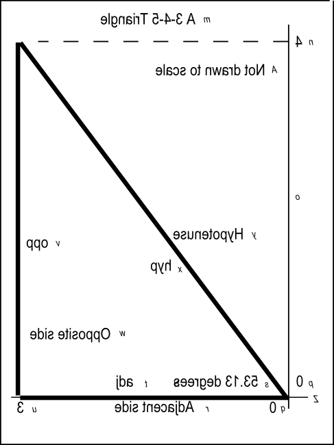
The base of the triangle will have a length of three units. Another side of the triangle will have a length of four units. The hypotenuse of the triangle will have still another length.
The angle at the origin
The base and the hypotenuse will form an angle at the origin opening outward to the right. As mentioned before, the base will be on the horizontalaxis. The side that connects the base and the far end of the hypotenuse will be parallel to the vertical axis.
Names for the three sides of the right triangle
Lets establish some names for the three sides of the right triangle when located on the graph board in this manner.
We will continue to refer to the hypotenuse as the hypotenuse and abbreviate it hyp . We will refer to the base as the adjacent side relative to the angle at the origin and abbreviate it adj . We will refer to the third side as the opposite side relative to the angle at the origin and abbreviate it opp .
Tactile graphics -- the file named Phy1020b1.svg
Much of the material in the next several paragraphs will only make sense to you if you are very familiar with the module named Manual Creation of Tactile Graphics .
When you downloaded the zip file named Phy1020.zip using the link given above , you should have found that the zip file contains a file named Phy1020b1.svg.
The purpose of this file is to make it possible for you to create tactile graphics for the right triangle. The procedure for creating the tactilegraphics is explained in the earlier module named Manual Creation of Tactile Graphics .
Image from file Phy1020b1.svg
For the benefit of any sighted persons that may be assisting you, Figure 2 shows a reduced version of the graphic contained in the file named Phy1020b1.svg. This is a mirror image of the imagethat is to be presented to the student after embossing. A non-mirror-image version is presented in Figure 19 .
| Figure 2 . Mirror image from file Phy1020b1.svg. |
|---|
 |
Page Setup information
If you use the IVEO Viewer software to print this svg file, you will need to set up the page by selecting Page Setup on the IVEO File menu. The Page Setup information for this file is shown in Figure 3 . These are the default settings for Letter (Portrait) in IVEO.
| Figure 3 . Page Setup for file Phy1020b1.svg. |
|---|
Paper List: Letter (Portrait)
Paper Width: 8.5 inchPaper Height: 11.0 inch
Orientation: portraitLeft Margin: 0.75 inch
Right Margin: 0.3 inchTop Margin: 0.75 inch
Bottom Margin: 0.3 inch |
Braille keys
Note that the file named Phy1020b1.svg and Figure 2 contain keys using the characters from "m" through "z" and "A" that can be used to createBraille characters during manual embossing. The key characters are shown in an oblique font that is smaller than the normal text. The purpose of these keys isexplained in the earlier module titled Manual Creation of Tactile Graphics .

Notification Switch
Would you like to follow the 'Accessible physics concepts for blind students' conversation and receive update notifications?