<< Chapter < Page Chapter >> Page >
The creation of this content was supported in some part by NSF grant 0538934.

Writing to file

Consider the function in [link] where a set of numbers in a one-dimensional array represents the resulting noisy signal is to be written to a file. This section will outline the steps required to create files.
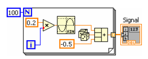
A screen capture of a noisy Signal function. There are three separate boxes comprised in this screen capture. From left to right, there is a small blue box containing the number 100. Followed bt a large box containing a diagram of the function, and then the last box is labeled the signal and it is an orange box.
Noisy Signal Function

Create a new G program, right click in the G programming window and select File Dialog from the Functions>>Programming>>File I/O>>Advanced Functions menu. Drag and drop the File Dialog function onto the G programming window.
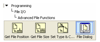
A screencap of a file dialog. There is a level listing at the top. The level nesting is as follows, with upper most level first. Programming, them File I/0, and then Advanced File Functions. Below Advanced File Functions is a horizontal list of four icons. From left to right the icons are labeled: Get file position, get file size, set Type &C... and finally, File Dialog. The File Dialog icon is contained within a light blue box.
File Dialog

The Configure File Dialog dialog box automatically appears to configure the function. Accept the default configuration shown in [link] to create a single file by clicking the OK button.

A typical Windows window. It is labeled 'Configure File Dialog [File Dialog]'. Contained in the window is a form with the top option selected 'Limit Selection to single item' below that the options 'File' and 'New or existing'. At the bottom of the form there are the buttons, 'ok', 'concel' and 'Help'.
Configure File Dialog

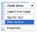
The resulting diagram after closing the configuration dialog box is shown in . Optionally, right click on File Dialog and select View As Icon from the pop-up menu. This will save some real estate in the G programming window.
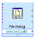
A screencap of a g file dialog. There is a 'selected path' option at the bottom of the icon.
G File Dialog
A screencap of a menu. From top to bottom the menu options are 'Visible Items', 'Open Front Panel', 'Size To Text', 'View As Icon' and 'Properties'. 'View As Icon' is highlighted blue.
View As Icon

From the Functions>>Programming>>File I/O menu select Open/Create File, Write Binary File and Close File functions.
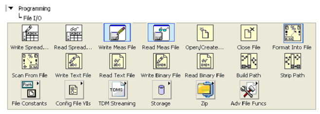
A screencap of 'File Input and Output Operators'. There are two main parts to this image. At the top there is a file listing with top level as 'Programming' and then 'File I/O'. The other part of the diagram is located below this file listing and is an array of three rows of icons with 7 icons on the first two row and 6 on the bottom row.
File Input and Output Operators

Arrange the File I/O operations as shown in [link] .

A row of 4 icons. The icon furthest to the left is highlighted in blue and labeled 'File Dialog'.
Open, Write and Close File Diagram

Right click on the operation (0:open) terminal of the Open/Create File function (highlighted in [link] ).

A row of 4 icons. The icon furthest to the left is highlighted in blue and labeled 'File Dialog'. The next icon is labeled 'operation (0:open)'.
File Create Operation

Select Create>>Constant from the pop-up menu.
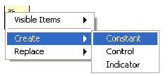
A screencap of a typical menu. The first menu has the item 'Create' selected and then points a nested menu with the item 'Constant' highlighted.
Create Operation Constant

Arrange the diagram to look as in [link] .

A row of four icons. The first icon is highlighted blue and labeled 'File Dialog'. Underneath the first icon is a blue box with the word 'open' contained in it. A line connects that blue box to the second icon.
Operation Constant

Click on the down arrow in the operation constant just created and select open or create from the pop-up menu.
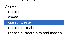
A screencap of a menu. The first item is 'open' and it has a check mark next to it. The fourth item is 'open and create' and it is highlighted blue.
Open or Create File Operation

The resulting updated operation constant value is shown in [link] .

A row of four icons. The first icon is highlighted blue and labeled 'File Dialog'. Underneath the first icon is a blue box with the word 'open or create' contained in it. A line connects that blue box to the second icon.
Create File to Write

Repeat the process to create a constant for the access (0:read/write) terminal (highlighted in [link] ).
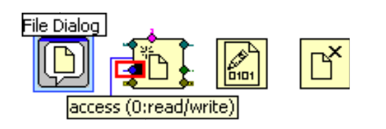
A row of four icons. The first icon is highlighted blue and labeled 'File Dialog'. Underneath the first icon is a blue box with the word 'access (0:read/write)' contained in it. A line connects that blue box to the second icon. The second icon is colored with little diamonds of different colors along the border of the icon.
File Access Mode

Set the constant to write-only . Re-arrange the block diagram to look like the diagram shown in [link] . At this point, the file is set to create a new file for writing.

A row of four icons. The first icon is highlighted blue and labeled 'File Dialog'. Underneath the first icon is a blue box with the word 'open or create' contained in it. Underneath the first icon is a blue box with the word 'write-only' contained in it. A line connects each of these blue boxes to the second icon.
Write Only Mode

Get the Noisy Signal function and wire its output data to the Data terminal of the Write to Binary File function.

A row of four icons. The first icon is highlighted blue and labeled 'File Dialog'. Underneath the first icon is a blue box with the word 'open or create' contained in it. Underneath the first icon is a blue box with the word 'write-only' contained in it. A line connects each of these blue boxes to the second icon. Below the second icon there is a box containing the phrase 'Noisy Signal' and A golden line connects this box to the third icon.
Writing Binary Data

Complete the diagram by connecting the Open , Write and Close file operations as shown in [link] .
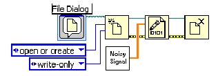
A row of four icons. The first icon is highlighted blue and labeled 'File Dialog'. Underneath the first icon is a blue box with the word 'open or create' contained in it. Underneath the first icon is a blue box with the word 'write-only' contained in it. A line connects each of these blue boxes to the second icon. Below the second icon there is a box containing the phrase 'Noisy Signal' and A golden line connects this box to the third icon. A light blue squiggly line connects the first icon to the second icon. Straight light blue lines and yellow squiggly lines connect the second icon to the third icon and the third icon to the fourth icon.
Writing to File G Program

When this G program is executed, the standard file dialog box appears. Name the file to be written signal.dat .
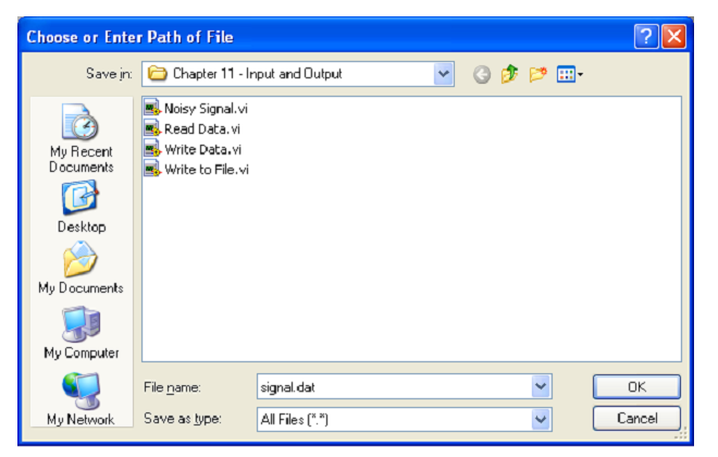
A screencap of a Windows window. It shows a create file dialog window.
Create File Dialog Box

Once the program completes executing, the signal.dat file is created and located in the location indicated by the path selected.
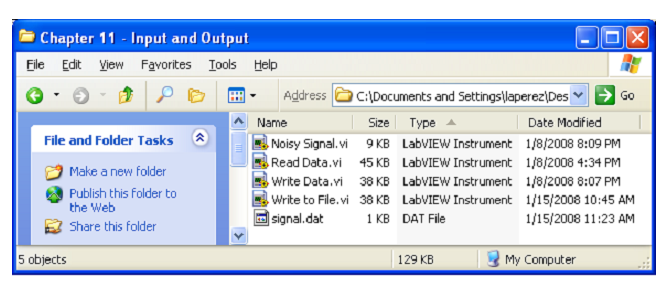
A screencap of a Windows window. It shows the location of Data File signal.dat.
Data File signal.dat

Reading from files

The signal.dat file created in the previous example will be used to read data from a file. As in the previous example, select the File Dialog , Open/Create File , Read from Binary File and Close File functions.

A row of four icons. The First icon is contained within a light blue box and is labeled 'File Dialog'.
Operators to Read Files

Create constants by right clicking on the operation (0:open) and access (0:read/write) terminals of the Open/Create File operation. Set the constants to open and read-only respectively (see [link] ).
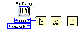
A row of four icons. The First icon is contained within a light blue box and is labeled 'File Dialog'. Below the first icon are two blue boxes the upper box contains the word 'open'and the bottom bos is labeled 'read-only. There are blues lines connecting these boxes to the second icon. A light blue squiggly line connects the first icon to the second.
Set to Open and Read-Only

Similar to creating arrays, drop an array constant in the G diagram, drop a numeric constant onto the array constant and set the data type representation to double . Wire this array constant to the data type terminal of the Read from Binary File function as shown in [link] .
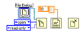
A row of four icons. The First icon is contained within a light blue box and is labeled 'File Dialog'. Below the first icon are two blue boxes the upper box contains the word 'open'and the bottom bos is labeled 'read-only. There are blues lines connecting these boxes to the second icon. A light blue squiggly line connects the fist icon to the second. A golden icon comprised of two rectangles is about icons 2 and 3 with a golden line connecting it to the 3rd icon.
Data Type to Read

In the Front Panel window, drop a Waveform Graph.
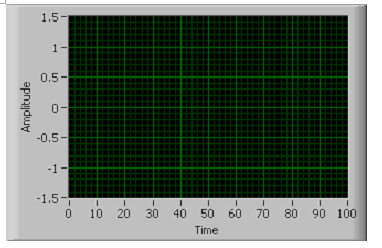
A screencap of a graph. Time is labeled from 0 to 100 on the x axis, and amplitude is labeled from -1.5 to 1.5 on the y-axis.
Graph for Data to be Read

With the data type specified, wire the data terminal of the Read from Binary File function to the Waveform Graph terminal as shown in [link] .
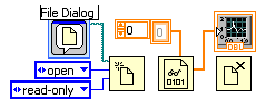
A row of four icons. The First icon is contained within a light blue box and is labeled 'File Dialog'. Below the first icon are two blue boxes the upper box contains the word 'open'and the bottom bos is labeled 'read-only. There are blues lines connecting these boxes to the second icon. A light blue squiggly line connects the fist icon to the second. A golden icon comprised of two rectangles is about icons 2 and 3 with a golden line connecting it to the 3rd icon. There is another golden line connecting the third icon to a little graph icon over the fourth icon.
Data to be Read

Complete the program by wiring refnum and error terminals of the Open/Create File , Read from Binary File and Close File functions as shown in [link] .
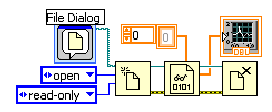
A row of four icons. The First icon is contained within a light blue box and is labeled 'File Dialog'. Below the first icon are two blue boxes the upper box contains the word 'open'and the bottom bos is labeled 'read-only. There are blues lines connecting these boxes to the second icon. A light blue squiggly line connects the fist icon to the second. A golden icon comprised of two rectangles is about icons 2 and 3 with a golden line connecting it to the 3rd icon. There is another golden line connecting the third icon to a little graph icon over the fourth icon. There are two yellow squiggly lines connection the second icon to the third and the third to the fourth.
Read Binary Data G Program

When this program is executed, a file dialog box appears. Select the signal.dat file and click OK .
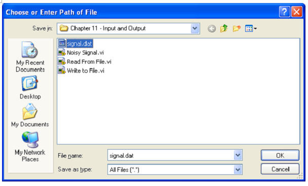
A screencap of a Windows window. It shows how to select a binary file to read from window.
Select Binary File to Read From

The binary data in signal.dat is read and plotted in a Waveform Graph . The result is shown in [link]
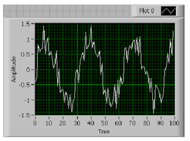
A screencap of a graph. Time is labeled from 0 to 100 on the x axis, and amplitude is labeled from -1.5 to 1.5 on the y-axis. Above the graph is a little square that says 'Plot 0'. The graph contains a jagged sin wav.
Read Data Graphed

Get Jobilize Job Search Mobile App in your pocket Now!

Get it on Google Play Download on the App Store Now


Source:  OpenStax, Introduction to g programming. OpenStax CNX. Mar 15, 2010 Download for free at http://cnx.org/content/col11192/1.1
Google Play and the Google Play logo are trademarks of Google Inc.

Notification Switch

Would you like to follow the 'Introduction to g programming' conversation and receive update notifications?

Ask