Figure 1
Published:
July 25, 2006
By Richard G. Baldwin
Java Programming Notes # 1540
This is the first part of a multi-part lesson designed to help you understand the use of lighting and illumination in 3D scenes produced using the Java 3D API.
Optical illusions
Creating scenes that appear to be three-dimensional on a flat two-dimensional screen is all about creating optical illusions. There are many important aspects to creating these optical illusions in 3D programming, not the least of which is lighting and illumination.
A 3D simulator program
In this lesson, I will teach you about, and show examples of many of the important features of scene illumination in the Java 3D API. I will also provide the source code for a complete Java 3D lighting simulator program that you can compile and run to experiment with light in the Java 3D API. I will explain how that program works in subsequent parts of this multi-part lesson.
Viewing tip
You may find it useful to open another copy of this lesson in a separate browser window. That will make it easier for you to scroll back and forth among the different figures, tables, and listings while you are reading about them.
Supplementary material
I recommend that you also study the other lessons in my extensive collection of online Java tutorials. You will find those lessons published at Gamelan.com. However, as of the date of this writing, Gamelan doesn't maintain a consolidated index of my Java tutorial lessons, and sometimes they are difficult to locate there. You will find a consolidated index at www.DickBaldwin.com.
The program that I will present in this lesson can be used to experiment with most of the lighting and illumination features of the Java 3D API either individually or in combination.
In order to compile and run this program, you will need to download and install the Java 3D API. As of the date of this writing, it was available at: http://java.sun.com/products/java-media/3D/. The online documentation was available at: http://download.java.net/media/java3d/javadoc/1.4.0/.
In addition, you will need to download and install either Microsoft DirectX or OpenGL.
Our perception of 3D visual objects
From time to time, I will make references to Chapter 6 of a document published by Dennis J. Bouvier at the following URL. http://java.sun.com/developer/onlineTraining/java3d/. For example, here is a quotation from Bouvier:
"In the real world, the colors we perceive are a combination of the physical properties of the object, the characteristics of the light sources, the objects' relative positions to light sources, and the angle from which the object is viewed. Java 3D uses a lighting model to approximate the physics of the real world."
The mathematical 3D model
According to Bouvier, Section E.2 of the Java 3D API Specification presents the mathematical equations of the Java 3D lighting model. Still quoting Bouvier,
"The lighting model equation depends on three vectors: the surface normal (N), the light direction (L), and the direction to the viewer's eye (E) in addition to the Material properties of the object and the light characteristics."
This program makes it easy for the user to vary the surface normal (indirectly), the light direction, and the Material properties of the object. The program does not make it easy for the user to modify the direction to the viewer's eye. However, the primary experimental object is a large sphere which, because of its curvature, inherently results in a wide range of directions from the object's surface to the user's eye.
Light sources
Returning to Bouvier,
"The lighting model incorporates three kinds of real world lighting reflections: ambient, diffuse, and specular. Ambient reflection results from ambient light, constant low level light, in a scene. Diffuse reflection is the normal reflection of a light source from a visual object. Specular reflections are the highlight reflections of a light source from an object, which occur in certain situations."
This program makes it easy for the user to experiment with all three types of sources, plus another form of illumination referred to as emissive color.
Two user interfaces
This program produces two user interfaces. One interface is the display of a 3D scene containing five spheres as shown in Figure 1.
Figure 1 |
(Note that the importation of the image into this HTML document introduced some visual artifacts that were not present in the original image produced by the program.)
The four small spheres
Four of the spheres are small with fixed reflective surface properties and a fixed number of facets. When illuminated with white light, or colored light corresponding to the color of the sphere, these spheres appear as white, red, green, and blue as shown in Figure 1.
The larger fifth sphere
The fifth sphere is larger. Almost everything about this sphere (other than its size and location) can be modified by the user through the second user interface shown in Figure 2.
Figure 2 |
The slider section
The user interface in Figure 2 consists of three main sections. The section at the top contains three sliders that are used to adjust the values of selected scene properties. The values indicated by the sliders are tied directly to the display shown in Figure 1, and the display changes in real time as each slider is adjusted to indicate different values.
A grid of radio buttons and text fields
The large middle portion of the interface contains a grid of radio buttons and text fields. The radio buttons are used to select the scene properties that will be modified by adjusting the sliders at the top of the user interface.
When a radio button is selected, the label above each slider changes to appropriately reflect the value of the scene property currently assigned to the slider. In addition, the values displayed in the text fields to the right of the selected radio button display the values indicated by the sliders, and the column headers for the text fields change to appropriately reflect the values of the scene properties currently associated with the selected sliders.
Shading and size
The four radio buttons at the bottom of the user interface are used to select between:
Figure 1 was produced as a large display using Gouraud shading. You will see examples of both types of shading as well as large and small displays later in this lesson.
More than 50 scene property values
The user can vary the surface reflective properties of the large sphere and can also modify various properties of the lights shown in Figure 1.
The user interface in Figure 2 provides more than 50 scene property values that can be modified by the user to change the reflective properties of the large sphere and the various properties of the lights. The ability for the user to modify the reflective surface properties of the large sphere makes it possible for the user to view the effects of those modifications in conjunction with varying light conditions.
Surface properties of the large sphere
The user can control almost all aspects of the following surface properties of the large sphere:
Five independent light sources
In addition, the user has control over the following five lights along with the properties shown:
An almost infinite number of combinations
Given the many properties of the five light sources and the many reflective properties of the spheres, the lights can be combined with the spheres to illuminate the scene in an almost infinite number of ways.
For example, having specified the various surface properties of the large sphere, the user can vary the properties of the lights and observe the manner in which the lights interact with the five spheres to illuminate the scene.
Real-time control
The properties of the large sphere and the lights are varied by selecting a radio button (see Figure 2) that corresponds to the property of interest and then adjusting the three sliders at the top of Figure 2. The display of the scene changes in real time as the user adjusts the sliders, making it possible to easily view the effects of fixing all of the properties but one and then varying that property across a range of values by moving a slider.
Large or small display
The user interface shown in Figure 2 also makes it possible for the user to select between a large and a small display. This was done mainly to support my publishing effort as I import the images into this tutorial lesson. Figure 1 shows the large display. You will see examples of the small display later.
Testing
This program was tested using J2SE 5.0, the Java 3D API version 1.4.0, WinXP and Microsoft DirectX. Note that it is also possible to use OpenGL instead of DirectX, but I haven't tried it.
Normally we would like to think that the silhouette of a sphere is a perfect circle. In the ideal case, that would be true. However, 3D computer graphics do not often reflect the ideal case.
How to draw a circle
When you were in elementary school, you probably learned how to use a compass to draw a circle. If you did it correctly, the circles were nice and smooth. Unfortunately, however, there are no compasses inside computers. Typically when we draw a circle with a computer, we compute the values that represent the circle at a set of regularly spaced points around the circumference of the circle and then connect those points with straight line segments. The closer the points are spaced, the better will be the representation of the circle.
How to draw a sphere
Similarly, when we draw a sphere with a computer, we typically compute the values representing the surface of the sphere at a set of regularly spaced points on the surface of the sphere and then connect those points with straight line segments. Those lines form the edges of flat polygons and it is this structure built from flat polygons that constitutes our representation of the sphere. Just as in the case of the circle, the closer together the points are on the surface of the sphere, the better will be our representation of the sphere.
The result is that our computer generated sphere will have facets much like the facets on a diamond.
Divisions in the Sphere constructor
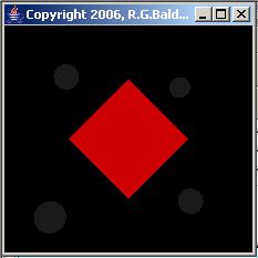
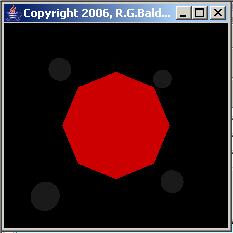
One of the overloaded constructors for the Sphere class in the Java 3D API has a parameter that Sun refers to as divisions. This parameter seems to specify the number of flat polygons that would be encountered in making one trip around the equator of the sphere. This is illustrated by the top two images in Figure 3.
 |
 |
 |
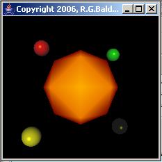 |
Figure 3 |
|
Silhouettes of a sphere
The upper-left image in Figure 3 shows the silhouette of a Sphere object constructed with a value of 4 for divisions. Granted it doesn't look much like a sphere. It looks like a square instead. However, that is what you get if you draw a circle by using straight line segments to connect only four points on the circumference of a circle.
The silhouette in the upper right of Figure 3 looks more like what we would expect to see for a sphere. This is what you get when you use straight line segments to connect eight equally spaced points on the circumference of the circle. It should be apparent that if I continue to increase the number of points on the circumference of the circle, the result will look more and more like a circle.
The Facets radio button
Returning now to Figure 2, the top radio button is labeled Facets. The text box immediately to the right of the radio button contains the value 50.0. That is the value that was used to draw the large sphere in Figure 1. In other words, during a trip around the equator of the large sphere in Figure 1, you would encounter 50 flat spots. The two top images in Figure 3 were produced with values of 4 and 8 respectively for the number of facets.
How to adjust the number of facets
To adjust the number of facets, you first select the Facets radio button. This causes the label above the top slider to read:
Facets on Surface of Large Sphere
You then move the slider to indicate the number of facets that you want your sphere to have, reading the output in the text field to the right of the radio button. The scale on the slider ranges from 0 to 100. However, if you attempt to specify a value less than 4 with the slider, the number of facets is clamped to 4.
An example display that shows the facets
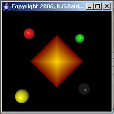
Now consider the bottom two images in Figure 3. These are the same two spheres shown as silhouettes in the top two images. However, the spheres in the bottom two images were not rendered as silhouettes. Rather, they were rendered in a three-dimensional form instead.
Vertices and polygons
Hopefully you can see some of the regularly-spaced points on the surface of the spheres (commonly referred to as vertices) as well as the connecting straight lines and the planar polygons that are formed by the vertices and the lines that connect them. It is these planar polygons that I refer to as facets.
Note, however, that even though the lower right sphere in Figure 3 was created with a Facet value of 8, the sphere actually has more than eight actual facets. When creating a sphere, the value that is specified for Facets in Figure 2 is the number of planar polygons that you would encounter in one trip around the equator of the sphere.
(Once again, I see some visual artifacts in the images in Figure 3 that were caused by importing them into this HTML document. I don't know if you will see them or not. However, they aren't in the original images so if you compile and run the program, you should not see them.)
How to use the program
Now you basically know how to use the program. To specify the number of facets for the large sphere in Figure 1, select the radio button labeled Facets and then use the top slider to specify the number of facets that occur during one trip around the equator of the sphere. This same procedure is used to adjust all of the scene properties except that many of the scene properties have three property values instead of only one property value.
Now that you know about the planar polygons (facets) that comprise the surface of the sphere, the next thing that you need to learn about is the shading model. In a nutshell, the shading model is used to determine the colors that will appear at the different points on each facet.
Two techniques for shading
Java 3D gives you two choices for determining those colors:
I'm not going to attempt to explain the technical details of these two shading techniques. Rather, I will simply suggest that you click on the two links provided in the above list to read what Wikipedia has to say about them. If you feel that you need more information on the topic after you read those explanations, go to Google and search for the keywords. I'm confident that you will find more material on the topic than you will have the time to read.
Example of Gouraud and Flat shading
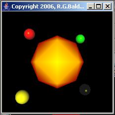
What I am going to do, however, is to show you an extreme example of the difference between the two shading techniques and show you how to select one or the other when you are running the program.
The image on the left in Figure 4 was produced using Gouraud shading. The image on the right was produced by applying Flat shading to the same 3D sphere.
 |
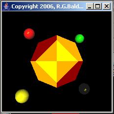 |
Figure 4 |
|
(Note that I made some minor color adjustments to the rightmost image in Figure 4 to cause the two dark brown polygons with the Flat shading to be distinguishable from the black background.)
Another example
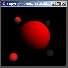
I confess that I chose the example in Figure 4 specifically to emphasize the difference between Gouraud and Flat shading. However, that is not the case for Figure 5.
 |
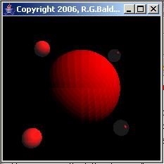 |
Figure 5 |
|
Figure 5 shows two renderings of the same large sphere. This is simply a red sphere with a Facets value of 50 being illuminated by a directional-light source located somewhere above my right shoulder and aimed directly at the center of the large sphere. The image on the left was rendered using Gouraud shading and the image on the right was rendered using Flat shading. Even with this relatively large number of facets, the Flat shading approach causes the facets to be very visible on the large sphere.
Not a high quality shading technique
As you can see, Flat shading is probably not what you would want to use for high quality 3D representations of visual objects. However, depending on your hardware, it may be much faster to compute Flat shading than Gouraud shading, so you may need to use it on some objects for improved speed if speed is an issue in your 3D applications.
Switching between the two shading techniques
Once you have established the scene properties and your scene is visible in the format of Figure 1, all you need to do to switch between Gouraud shading and Flat shading with this program is to select the appropriate radio button at the bottom of the control panel shown in Figure 2. In a subsequent installment of this lesson, I will teach you how to write the Java code to switch between the two types of shading.
Figure 6 gives us another look at the four small spheres.
Figure 6 |
Calibration spheres
I placed these spheres in the scene to serve a calibration function. Each sphere has fixed surface reflection properties (except that they do switch between Gouraud shading and Flat shading in accordance with the selected shading button). As I add new light sources to the scene for the purpose of illuminating the large sphere shown in Figure 1, I can check to see how the small spheres are being illuminated by those same light sources. The results should be very predictable.
The large sphere in Figure 1 is centered at the origin in the three-dimensional space having coordinates of x, y, and z. The x-axis is the horizontal axis with positive values to the right. The y-axis is the vertical axis with positive values going up the screen. The z-axis is perpendicular to the screen with positive values coming out of the screen toward the viewer.
The location coordinates for the four small spheres are given in Table 1 later in this lesson. The red and blue spheres in Figure 6 each have their centers on the z-plane. In other words, their z coordinate value is 0.0. A line drawn through their centers would lie on the z-plane and would go through the origin of the z-plane. However, as you can see, their x and y coordinates are not zero. Rather, the line connecting their centers would be at an angle of 45-degrees relative to the x-axis.
The locations of the white and green spheres is such that they lie on a tilted plane that goes through the origin and also goes through the line connecting the centers of the red and blue spheres. The white sphere is closest to the viewer (positive z-coordinate value) while the green sphere is further away from the viewer (negative z-coordinate value). If you were to view the four small spheres from a vantage point perpendicular to that plane, they would lie on the four corners of a square inscribed on that plane.
Location and nature of the light source
While the surface reflection properties and the locations of the four small spheres are fixed, the locations of light sources that can be used to illuminate them are not fixed.
The light source that is illuminating the four spheres in Figure 6 is an invisible omnidirectional source of white light located at the origin in the three-dimensional space. This places the light source in the middle of the four spheres. As you can see, the appropriate portion of each of the spheres is illuminated for an omnidirectional-light source at that location.
I'm unaware of any source of light in the physical world that behaves this way. The light source itself is invisible, but the impact of that light source on the spheres is visible.
This is sort of like having an omnidirectional source of heat at the origin that causes the spheres to glow in their own distinctive colors when they become warm. (It would probably be possible to build a system in the physical world that behaves in this fashion.)
For the record, this light source is an object of the PointLight class, which I will discuss in more detail later.
The scene properties
The scene properties for the four small spheres are shown in Table 1.
|
White |
Red |
Green |
Blue |
|
| Facets | 50 | 50 | 50 | 50 |
| Shininess | 128 | 128 | 128 | 128 |
| Emissive Color | 0.1, 0.1, 0.1 | 0.1, 0.1, 0.1 | 0.1, 0.1, 0.1 | 0.1, 0.1, 0.1 |
| Ambient Color | 1.0, 1.0, 1.0 | 1.0, 0.0, 0.0 | 0.0, 1.0, 0.0 | 0.0, 0.0, 1.0 |
| Diffuse Color | 1.0, 1.0, 1.0 | 1.0, 0.0, 0.0 | 0.0, 1.0, 0.0 | 0.0, 0.0, 1.0 |
| Specular Color | 1.0, 1.0, 1.0 | 1.0, 1.0, 1.0 | 1.0, 1.0, 1.0 | 1.0, 1.0, 1.0 |
| Coordinates | -0.5, -0.5, 0.5 | -0.5, 0.5, 0.0 | 0.5, 0.5, -0.5 | 0.5, -0.5, -0.0 |
| Table 1 | ||||
The column headers identify each of the spheres according to the dominant colors of the spheres in Figure 6. The row headers identify each of the scene properties in the same order as Figure 2 with the addition of the location coordinates of the spheres in the bottom row.
Color information
For the rows that contain color (surface reflection) information, the three values in each cell correspond to the values for red, green, and blue respectively.
(In Java 3D, color values are given in the range from 0.0 to 1.0 as opposed to the possibly more familiar 8-bit integer range from 0 to 255.)
The White sphere
For example, the information in the Diffuse Color cell for the White sphere indicates that this sphere will reflect red, green, and blue light from a diffuse light source equally well.
Therefore, when this sphere is illuminated by a diffuse source of white light, it will appear to be white or gray depending on the intensity of the light.
The Red sphere
On the other hand, the information in the Diffuse Color cell for the Red sphere indicates that it will reflect red light very well, but won't reflect green or blue light at all.
Therefore, when this sphere is illuminated by a diffuse source of white light, it will appear to be some shade of red depending on the intensity of the light. The same is true if it is illuminated by a diffuse source of red light.
Location coordinate information
For the bottom row containing location coordinate information, the values in each cell correspond to the x, y, and z coordinates values respectively. These coordinates specify the locations of the four small spheres that I attempted to describe verbally earlier.
Similarities and differences between the small spheres
Much of the information in Table 1 will mean more to you as we proceed through an explanation of the various scene properties. For now, suffice it to say that many of the values are the same among the four spheres. The major differences between the small spheres are the ambient color, the diffuse color, and the location coordinates. The emissive color and the specular color of all four spheres are the same, as are the number of facets and the shininess.
That brings us to the scene property that is probably the easiest to deal with: Emissive Color.
Here is part of what Wikipedia has to say about emissive light (not necessarily with respect to the Java 3D API):
"The materials also specify "emissive light" for the polygons. The emissive light is light that the polygon itself emits (for example your monitor). In case the polygon is emissively lit you can think of it as a visible light source, which is NOT emitting light to the surrounding objects!"
Here is some of what Bouvier has to say about emissive color, specifically with regard to the Java 3D API:
"The Material object allows the specification of an emissive color. This can be used to create the effect of a
glow-in-the-dark object. Having an emissive color does not make the visual object a light source; it will not
illuminate other visual objects."
A stand-alone scene property
The emissive color scene property is easy to deal with because, unlike many of the other scene properties, it stands completely on its own and doesn't require interaction with other scene properties. As described above, a visual object can emit its own light. This is controlled by the emissive color scene property shown in Figure 2. When a visual object emits its own light, it does not illuminate adjacent objects.
Unlike the physical world
Once again, I am unaware of any source of light in the physical world that behaves in this manner. Most illuminated objects that I am aware of will cause adjacent objects to also become illuminated to some extent.
Color and intensity is variable
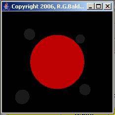
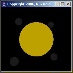
In any event, given that restriction, the emissive color scene property can be used to cause an object to be illuminated in any color at any of the allowable intensity levels. This is shown in Figure 7 where the large sphere is illuminated with four different colors and intensity levels by emitting its own light.
 |
 |
 |
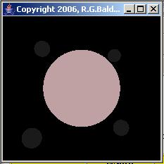 |
Figure 7 | |
Small spheres are not illuminated by the large sphere
Note that the small spheres in the scene in Figure 7 are not illuminated by the light being emitted by the large sphere. However, if you look very carefully, you may be able to see that each of the small spheres also emits a small amount of light on its own. This is indicated by the values in the Emissive Color row of Table 1.
No shading, Gouraud or otherwise
Also note that even though the visual objects in Figure 7 are spheres, there is no shading to create an optical illusion causing them to look like spheres. Rather, they look more like colored disks. Visual objects that are illuminated by emitting their own light are not shaded in the Java 3D API. Rather, the entire surface of the object is illuminated uniformly.
How to use emissive light
To illuminate the large sphere by causing it to emit its own light, select the Emissive Color radio button in Figure 2. Then adjust the three sliders to cause the color mix and the intensity of the illumination to be what you need.
The color values that you specify by adjusting the sliders will be displayed in the three text fields next to the radio button in real time as you adjust the sliders. Also, the color and intensity of the large sphere in the display will change in real time as you adjust the sliders.
Things are about to get a little more complicated. Up to now, just about everything that we have done has been done on a standalone basis. However, from this point forward, you will have to think in terms of the reaction of a surface having specified reflection properties to a light source having its own set of light-radiation properties.
Light sources and reflections
We saw earlier what Bouvier has to say about the three kinds of real-world lighting reflections, and the simulation of those three kinds of reflections in the lighting model of the Java 3D API:
At this point, we are interested in ambient reflections only. We will take up diffuse and specular reflections later in the lesson.
A link between ambient color and ambient light
Figure 2 contains the following two radio buttons, which are the main topic of this portion of the lesson:
The Ambient Color radio button makes it possible for you to control a set of surface reflection properties that will cause the large sphere to react only to light radiated from an object constructed from the AmbientLight class.
The AmbientLight radio button makes it possible for you to control a set of properties belonging to an object constructed from the AmbientLight class.
What is ambient light?
In the Java 3D API, ambient light is light that arrives uniformly from all directions. All visual objects in a scene that is illuminated by ambient light will be uniformly illuminated according to their surface reflection properties for ambient light.
A real-world example
As a real-world example, a sphere illuminated by ambient light is similar to what you would experience if you were to hang a basketball from a clothes line in an open field on a very cloudy day. To a large extent, the basketball would be uniformly illuminated over its entire surface (although the top may be a little brighter than the bottom).
Although the sun would have been the original (highly directional) source of the light, that light would have been so heavily filtered, scattered, and reflected by the cloud layer, the ground, and the other physical objects in the region that the light would appear to come from all directions uniformly. As a result, there would be no shadows and the entire surface of the basketball would be almost uniformly illuminated. Light sources constructed from the AmbientLight class in the Java 3D API simulate this kind of light with the illumination being completely uniform over the surface of illuminated objects.
How does ambient color (reflection) fit into this picture?
Ambient surface reflection properties and light radiated from AmbientLight objects are uniquely tied together. Both must exist with non-zero states for either to have an impact on the scene. If there is no ambient light illuminating the scene, changing the AmbientLight surface reflection properties of a visual object will have no impact on the scene. Conversely, if there are no visual objects in the scene having non-zero values for the ambient surface reflection properties, even high intensity ambient light sources will have no impact on the scene.
Examples of ambient light
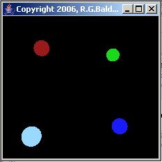
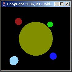
Four examples of the interaction between ambient surface reflection properties and an ambient light source are shown in Figure 8.
 |
 |
 |
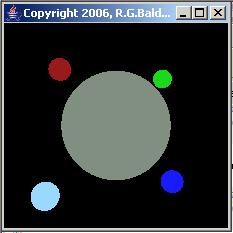 |
Figure 8 | |
The ambient light source
For all four images shown in Figure 8, the color and intensity properties of the ambient light source were:
This is colored light. It is not white light because there are different intensity levels from each of the primary colors.
The large sphere is not initially visible
The large sphere is not visible in the upper-left image in Figure 8. This is because all three ambient reflection properties were set to 0 for the large sphere for this image. However, the four small spheres are visible. This is because each of the small spheres has non-zero values for its ambient reflection properties as shown in the Ambient Color row of Table 1.
Reflection color properties react to light source colors
In order for a visual object to be visible when subjected to any light source in the Java 3D API, the reflection color properties of the object must contain color components that are also contained in the light. For example, a visual object having only red reflection properties subjected to a light source having only green or blue color components will appear to be black.
When there is a color match between a color component in the surface reflection properties and a color component in the light source, the numeric values of the matching color components are used to determine the intensity of that color component in the resulting overall color of the visual object.
Ambient reflection properties react to ambient light source
The AmbientLight color values for the light source combined with the ambient reflection properties for each of the small spheres resulted in the colors shown for the small spheres in each of the images in Figure 8.
For example, the small sphere in the lower left of each image doesn't appear to be white as was the case in Figure 1. Rather, even though the ambient reflection properties of this sphere contain the maximum possible values for red, green, and blue, (and the sphere would appear to be white when subjected to white light) in this case it was subjected to colored light and therefore appears to be more blue than white.
Add a red reflection property to the large sphere
The red ambient reflection property value for the large sphere was increased from 0.0 to 1.0 for the upper-right image in Figure 8. This caused the large sphere to become visible with a somewhat subdued red color.
(Even though the value of the red reflection property for the large sphere was increased to its maximum possible value, the contribution of red light in the source was only at half its maximum value, resulting in a red color with subdued intensity.)
Add some green and blue reflection capability
For the lower-left image in Figure 8, the green ambient reflection property value for the large sphere was increased from 0.0 to 0.75 producing the olive drab color shown.
For the lower-right image, the blue ambient reflection property value for the large sphere was increased from 0.0 to 0.5, producing the gray color shown.
Reversed property value order
After increasing the ambient reflection property values for the large sphere as described above, the value order of the ambient reflection property values for the large sphere was exactly the reverse of the value order of the ambient color property values for the light source as shown below:
This resulted in the large sphere appearing to be colored gray in the lower-right image of Figure 8. The color gray suggests that the color property values from the light source were combined with the color property values from the large sphere in such a way as to produce nearly equal contributions of each of the primary colors in the final color. So far, I have been unable to find the specifications as to how color values in the reflection properties are combined with color values in the light source. However, I suspect that they are simply multiplied together. If so, that would result in a final overall color for the large sphere with the following color component values:
red = 0.5, green = 0.56, blue = 0.5
As suggested above, these color component values are nearly equal, which would result in a gray color.
This further demonstrates that the color of a visual object depends on a combination of the reflective color properties of the object and the radiated color properties of the light source.
No shading
Another important aspect of ambient light is also illustrated by Figure 8. In particular, there is no shading with ambient light. This is because the ambient light is assumed to originate uniformly from all directions simultaneously so that the entire surface of the visual object is assumed to be uniformly illuminated.
Doesn't contribute to the 3D optical illusion
Because of the lack of shading, neither emissive color nor ambient color contribute very much to the optical illusion that is required to cause images displayed on a two-dimensional screen to appear to be three dimensional. For that, we need some form of directional light, and that is where we are going next.
Referring back to Figure 2, we have two more kinds of reflective properties to consider:
We also have three more kinds of light sources to consider.
In addition, we have a shininess property that I have been ignoring up to this point.
All possible combinations
Any of the three kinds of light sources in the above list will react with either of the two kinds of reflective properties in the above list. Furthermore, the shininess property comes into play any time specular reflection is involved. This gives us six combinations of sources and properties that we need to understand. We also need to understand how and when shininess impacts the results and to understand the existence or lack of shadows. This leaves us with the following major topics to cover in the remainder of this installment of the lesson:
What is diffuse reflection?
Here is part of what Wikipedia has to say about diffuse reflection:
"Diffuse reflection is the reflection of light from an uneven or granular surface such that an incident ray is seemingly reflected at a number of angles. It is the complement to specular reflection. If a surface is completely nonspecular, the reflected light will be evenly spread over the hemisphere surrounding the surface (2×π steradians).
The most familiar example of the distinction between specular and diffuse reflection would be matte and glossy paints as used in home painting. Matte paints have a higher proportion of diffuse reflection, while gloss paints have a greater part of specular reflection."
What is a directional-light source?
Bouvier has this to say about light radiated from a DirectionalLight object in Java 3D:
"A DirectionalLight source approximates very distant light sources such as the sun. Unlike AmbientLight sources, DirectionalLight sources provide light shining in one direction only. For objects lit with a DirectionalLight source, the Light vector is constant. ... Since all light vectors from a DirectionalLight source are parallel, the light does not attenuate. In other words, the intensity of a DirectionalLight source does not vary by the distance between the visual object and the DirectionalLight source."
Assumptions regarding a DirectionalLight source
I will paraphrase much of what I have learned about the DirectionalLight class. An object of the class is intended to simulate light sources that satisfy the following assumptions:
Cannot directly control the actual location of a directional-light source
As with the other kinds of light sources, you can control the relative intensity of each of the color components radiated by a directional-light source.
However, unlike point-light and spotlight sources, you cannot control the actual location of the directional-light source. The location of the light source is assumed to be somewhere far outside the 3D space enclosed by the scene.
Can control the direction to the directional-light source
However, you can control the direction of the light being radiated by the directional-light source. Since all light radiated by a directional-light source is parallel, this means that you can also control the direction to the directional-light source.
Controlling the direction of the light
To control the direction of the light being radiated from a directional-light source, you define a 3D vector with its tail at the origin in the 3D space. You define the vector by providing the coordinates of the head of the vector. The direction of the light is then assumed to be parallel to the direction of that vector. To change the direction of the light, you change one or more coordinate values that specify the location of the head of the vector.
A lever analogy
In effect, the source is located on the end of a very long lever that goes through and pivots at the origin in 3D space. The direction of the light is parallel to the long dimension of the lever.
Your vector can be thought of as representing a very short segment of that lever as it emerges from the origin on the opposite side of the origin from the directional-light source. You can rotate your vector in 3D space by changing the coordinates of the head of the vector. This has the effect of causing the other end of the lever to rotate in the reverse direction in 3D space. This, in turn causes the location of the source on the end of the lever to move.
You can think of this as a 3D lever with the length on one side of the fulcrum (pivot point) being much longer than the length on the other side of the fulcrum. When one end goes down, the other end must go up, and vice versa.
Behind, up, and to the right
For example, if you want to cause the directional-light source to be up to the right and behind the viewer, you cause the vector to point down to the left and into the screen. This can be accomplished by using the following coordinate values for the head of the vector:
These are the vector coordinates that were used along with a directional-light source to illuminate the scene in Figure 1.
The light source is never visible
As was the case in Figure 6 where the light source was located between the small spheres, the light source itself is never visible in Java 3D. Rather, light sources in Java 3D appear to radiate invisible light that somehow gets magically converted into visible light by the visual objects on which the invisible light impinges. (See my earlier example in the section entitled A heat analogy.)
For example, if you want to create an image of a table lamp illuminating a scene, you can put a PointLight object at the location of the lamp to illuminate the scene, but you then need to make certain that the lamp itself is illuminated. You might consider causing the lamp to have emissive color so that it will illuminate itself.
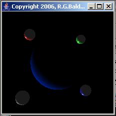
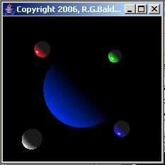
The view from space
The large sphere in the upper-left image in Figure 9 shows what an astronaut might see as her capsule in a stationary orbit above the Earth emerges from the dark side of the Earth.
 |
 |
 |
 |
Figure 9 | |
This occurs as the Earth (and the capsule) rotates causing the sun to emerge from behind the earth. (The four small spheres represent space stations that are also in stationary orbits above the Earth.)
The sun is behind the Earth
In this image, the directional-light source (the sun) is behind the large sphere (the Earth) and is far outside the scene to the lower left. The direction of the light is roughly toward the astronaut's right shoulder. The coordinates of the direction vector for this image are:
The Earth continues to rotate
As the Earth continues to rotate, the sun continues to swing around the Earth as shown in the upper-right image in Figure 9. This exposes a much greater portion of the Earth to sunlight. In this case, the light direction is parallel to the z-plane shining from the lower left towards the upper right.
The coordinates of the direction vector for this case are:
The sun is behind the astronaut
In the lower-left image in Figure 9, the sun has swung further around the Earth to the point that the astronaut is directly between the sun and the Earth and is facing the Earth. In other words, the astronaut is facing the Earth with the sun directly behind her back. The light direction is perpendicular to the z-plane going into the screen. For this case, the coordinates of the direction vector are:
Off into the sunset
In the lower right of Figure 9, the sun has progressed exactly half way around the Earth relative to the upper-right image. In a short while, the sun will go behind the Earth again. In this case, the light direction is once again parallel to the z-plane shining from the upper right towards the lower left. The coordinates for the direction vector for this case are:
I will introduce this topic by quoting Bouvier:
"The Material object specifies ambient, diffuse, specular, and emissive colors and a shininess value. Each of the first three colors is used in the lighting model to calculate the corresponding reflection. ... The shininess value is only used in calculating specular reflections. ... The shininess value controls the spread range of viewing angle for which a specular reflection can be seen. Higher shininess values result in smaller specular reflections."
Specifying the shininess property value
The value for the shininess property is specified in this program by selecting the Shininess radio button in Figure 2 and adjusting the top slider. When you select the radio button, the label above the top slider changes to read "Shininess of Surface of Large Sphere." The adjustment range for the slider is set to show 0 as the minimum and 128 as the maximum.
The setShininess method
Here is some of what Sun has to say about the setShininess method of the Material class:
"Sets this material's shininess. This specifies a material specular scattering exponent, or shininess. It takes a floating point number in the range [1.0, 128.0] with 1.0 being not shiny and 128.0 being very shiny. Values outside this range are clamped."
Therefore, if you adjust the slider to a value between 0 and 1, the value will be automatically clamped at 1.0 when the setShininess method is called to set the shininess property value.
I will discuss the shininess property in more detail in the next section.
What is specular reflection?
One good way to understand specular reflection is to contrast it with diffuse reflection. Here is part of what Wikipedia has to say on the topic:
"Specular reflection is the perfect, mirror-like reflection of light (or sometimes other kinds of wave) from a surface, in which light from a single incoming direction is reflected into a single outgoing direction. Such behaviour is described by the law of reflection, which states that the direction of outgoing reflected light and the direction of incoming light make the same angle with respect to the surface normal; this is commonly stated as θi = θr.
This is in contrast to diffuse reflection, where incoming light is reflected in a broad range of directions. The most familiar example of the distinction between specular and diffuse reflection would be matte and glossy paints. While both exhibit a combination of specular and diffuse reflection, matte paints have a higher proportion of diffuse reflection and glossy paints have a greater proportion of specular reflection. Very highly polished surfaces, such as high quality mirrors, can exhibit almost perfect specular reflection."
Examples of specular reflection
Excellent examples of specular reflection are exhibited by the white spots on the red, green, and blue spheres in Figure 1. Those same spheres also exhibit specular reflection in Figure 3, Figure 6, and Figure 9. Because of the shading involved, even the white sphere in Figure 6 exhibits specular reflection.
Shininess and specular color property values
Table 1 shows the shininess and specular property values that are hard-coded into the program for the small spheres. The value of 128 for shininess specifies that the size of the specular reflection is to be as small as possible. The color values for specular color specify that the specular reflection will be white for all four of the small spheres, regardless of their diffuse color or ambient color.
Specular reflections on the large sphere
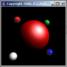
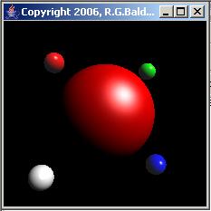
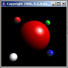
Figure 10 shows the result of varying the shininess property value on the large sphere.
 |
 |
 |
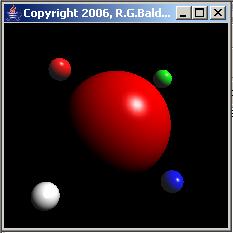 |
Figure 10 | |
The scene property values
The important scene property values for the large sphere for the images shown in Figure 10 are provided in Table 2.
|
Property |
Property Value |
| Facets | 100 |
| Shininess | 16, 32, 64, 128 |
| Diffuse Color | 1.0, 0.0, 0.0 |
| Specular Color | 1.0, 1.0, 1.0 |
| Directional Light Color | 1.0, 1.0, 1.0 |
| Directional Light Vector | -1.0, -1.0, -1.0 |
| Table 2 | |
As you can see from Table 2, the large sphere is very smooth with a value of 100 for Facets. The diffuse color is red and the specular color is white. The scene is illuminated by white directional-light source with the direction of the light being toward the screen, down, and to the left.
Varying values for the shininess property
The upper-left image has a shininess property value of 16. Starting with the upper-left image and going from left to right, top to bottom, the value of the shininess property is doubled for each image. This results in the maximum possible shininess value of 128 for the lower-right image.
As described earlier, the size of the specular reflection decreases as the value of the shininess property value increases.
One of the characteristics of the Java 3D API that detracts somewhat from the realism of 3D scenes is that visual objects don't cast shadows. This is illustrated by the scene in Figure 11.
Figure 11 |
The scene properties
The important scene properties for Figure 11 are shown in Table 3.
|
Property |
Property Value |
| Facets | 100 |
| Shininess | 64.0 |
| Diffuse Color | 0.0, 1.0, 1.0 |
| Directional Light Color | 1.0, 1.0, 1.0 |
| Directional Light Vector | -0.5, -0.5, 0.0 |
| Table 3 | |
Illumination of the scene
The scene in Figure 11 is illuminated exclusively by a directional-light source located far away, down, and to the right. The vector for the directional-light source is focused on the center of the red sphere.
There should be some shadows
The light source is in the same plane as, and is in alignment with the large sphere and the small red and blue spheres. The location and direction of the light source is such that the small blue sphere should cast a shadow on the large sphere, and the large sphere should completely block out any light from reaching the small red sphere. As you can see, that doesn't happen.
Opaque and transparent at the same time
Visual objects in Java 3D behave as if they are both transparent and opaque. They are opaque because incident light from a light source will cause them to be illuminated according to their diffuse and/or specular color properties. They are transparent because the light goes right through them without being attenuated and illuminates other visual objects that are located behind them.
In my discussion of the DirectionalLight class, I explained that an object of the DirectionalLight class is intended to simulate light sources that satisfy the following assumptions:
Must be far far away
It is the first assumption in the above list that causes the remaining three assumptions to be reasonably valid. Except for the sun, very few light sources behave according to the assumptions listed above (and as I will explain later, even the sun doesn't satisfy these assumptions to the letter).
Most light rays are not parallel
For example, except for lasers, the light rays that are radiated by most light sources do not travel in parallel paths. Therefore, most light sources will not satisfy the second assumption in the above list.
No flat and wide wavefront
Although the light radiated by high-quality lasers does come very close to traveling in parallel paths, the beam of light produced by a laser is usually very narrow.
The wavefront from a laser is probably very close to being flat, but normally the beam isn't wide enough to illuminate an entire scene. Therefore, most lasers won't satisfy the third assumption in the above list.
Rather, a laser is more akin to a SpotLight object than a DirectionalLight object. (I will discuss the use of the SpotLight class later in this lesson.)
Attenuation of light energy does occur
For most light sources, the light energy is attenuated with distance from the source. I will explain the reasons later.
Even the sun doesn't satisfy the assumptions
The light rays from the sun do not travel in parallel paths. Rather, they shoot out in all directions, some in the direction of the Earth and some in other directions.
The light waves from the sun do not have a flat wavefront. In general, light waves from the sun probably have a spherical wavefront.
There is attenuation of light energy as you get further and further away from the sun. If you could travel to Pluto and look back at the sun, it would probably appear to be very dim. (See the recent programming on Pluto on the Discovery Channel.)
Reasonable approximations
However, because the sun is so far away, the curvature of the wavefront across a distance equivalent to the width a Java 3D scene is very small. Therefore, the wavefront can be assumed to be flat.
While there is attenuation of the light energy from the sun across the vastness of space, the attenuation across the distances involved in a Java 3D scene is so small as to be negligible. Therefore, it is reasonable to assume that there is no attenuation of sunlight across a scene.
Because of the enormous distance from the sun to the earth, the angle between the light rays at the two outer edges of a Java 3D scene is extremely small. Therefore, it is reasonable to assume that the light rays travel in parallel, although this is clearly not the case.
A more realistic light source
The PointLight class is intended to provide a more realistic simulation of typical man-made light sources. The energy from an omnidirectional-light source radiates uniformly in all directions in 3D space. You can think of the light waves that are radiated from an omnidirectional-light source as approximating a series of spherical wave fronts. (This is similar to the two-dimensional circular wave fronts that radiate from the impact point of a pebble that is tossed into a pond.) As the spherical wavefront moves further and further from the source, the sphere grows larger and the area of the spherical wavefront increases.
Conservation of energy
A finite amount of light energy is encapsulated in the wavefront. As the wavefront moves further and further from the source and the total area of the wavefront increases, the amount of energy per unit area of the wavefront decreases. Eventually the amount of energy in an area the size of the capture area of your eyeball becomes negligible and you can no longer see the distant light.
Telescopes
To compensate for this spreading effect of light energy as the distance to the source increases, astronomers use mirrors with very large areas to capture light waves from distant stars (our sun is a star). These mirrors are shaped so as to capture the light energy over a very large area and to reflect and focus that light energy into a very small area. That small area is where you put your eyeball, (or possibly your camera lens) to view or record the image made up of the light that is captured by the large mirror. Thus, telescopes with large mirrors tend to be more sensitive to light from distant stars than telescopes with small mirrors. They are definitely more sensitive than the naked eye.
(Although you may not be aware of it, you are probably already familiar with this concept. The large devices commonly referred to as satellite dishes perform the same function except that they are used to capture radio waves instead of light waves.)
Location of a PointLight object
An object of the PointLight class can be placed anywhere in your 3D universe either inside or outside of the scene being illuminated. Remember, however, that if you place it inside the scene, it will not be visible. However, the impact that it has on the visual objects in the scene will be visible.
Color, intensity, and attenuation
As usual, you can specify the color and intensity properties of a light source based on a PointLight object. In addition, you can specify an attenuation factor made up of three values that simulate the spreading effect of light energy discussed above.
What does Sun have to say?
Here is some of what Sun has to say about an object of the PointLight class.
"The PointLight object specifies an attenuated light source at a fixed point in space that radiates light equally in all directions away from the light source. PointLight has the same attributes as a Light node, with the addition of location and attenuation parameters. ... A point light contributes to diffuse and specular reflections but it does not contribute to ambient reflections."
Brightness decreases with distance from the source
The energy from a PointLight object is attenuated by multiplying the intensity of the light by the attenuation factor. Two of the three values that make up the attenuation factor cause the brightness produced by a PointLight object to decrease as distance from the light source increases.
Composition of the attenuation factor
The three values that make up a PointLight object's attenuation factor are:
Formulation of the attenuation factor
According to Sun, the brightness of a PointLight object is attenuated by the reciprocal of the sum of:
Stated in equation form, this results in a scale factor, S, being applied to the light intensity produced by the PointLight object where:
S = 1/(C + L*D + Q*D*D)
Default values
By default, this program causes the constant attenuation value to be1.0 and the other two attenuation values to be 0.0. This results in no attenuation in the default case.
Allowable attenuation value ranges
Because of the reciprocal used in the formulation of the attenuation factor, a constant attenuation value less than 1.0 would result in a gain in light intensity rather than a loss of light intensity. This is completely at odds with reality. Therefore, this program does not allow constant attenuation factors less than 1.0. The program also doesn't allow constant attenuation factors greater than 2.0. The other two attenuation values are allowed to range from 0 to 0.2.
Select the radio buttons and adjust the sliders
As is the usual procedure with this program, you specify the point-light color, location, and attenuation values by selecting the appropriate radio buttons in Figure 2 and then adjusting the sliders to specify the values.
The sun and four planets
Figure 12 shows a 3D scene of a beautiful golden sun providing daylight illumination for four orbiting planets.
Figure 12 |
There's something wrong with this picture
However, there is something with Figure 12. Can you tell what it is?
The problem with Figure 12 is that the sun depicted by the large sphere isn't really providing daylight illumination for the four planets. After the sun burns itself out and becomes a large black cinder, the four planets are still bathed in daylight as shown in Figure 13.
Figure 13 |
The sun is a facade
Although Figure 12 looks fairly realistic, the sun is merely a facade. That's why it doesn't matter to the planets that is has been eliminated from Figure 13.
The large sphere in Figure 12 is self-illuminated by the emissive color values shown in Table 4 and the four planets are illuminated by a point-light source.
|
Property |
Property Value |
| Facets | 100 |
| Shininess | 64.0 |
| Emissive Color | 1.0, 1.0, 0.5 |
| PointLight Color | 1.0, 1.0, 0.5 |
| PointLight Location | 0.0, 0.0, 0.0 |
| PointLight Attenuation | 1.0, 0.0, 0.0 |
| Table 4 | |
Emissive color is not a light source
As you will recall from an earlier section, a visual object that is self-illuminated by emissive color does not function as a light source. It cannot illuminate other visual objects nearby.
The four planets in Figure 12 and Figure 13 are illuminated by a PointLight object having the color, location, and attenuation values shown in Table 4.
Location of the point-light source
Both the large sphere and the point-light source are located at the origin in the 3D space in Figure 12. In other words, the point-light source is located at the center (inside) of the large sphere, causing it to be in the correct location to illuminate the four planets that orbit the large sphere.
Why wasn't the large sphere illuminated by the PointLight source?
By now, you may be wondering why the inclusion of a point-light source inside the large sphere doesn't illuminate it from the inside out. If so, that is an excellent question. Unfortunately, the answer to the question, which involves the direction of the normal vectors, is too complicated to answer in this lesson. Perhaps I will provide an answer in some future lesson. In the meantime, I will simply have to leave that question as an exercise for the student.
Matching colors
In addition to the fact that the sun and the point-light source are co-located in Figure 12, the color of the point-light source is the same as the color of the large sphere, causing its color to properly illuminate the white planet and the white specular reflections on all four planets.
Attenuation of a point-light source
As I explained earlier, a point-light source has an attenuation property that involves three values. The formulation of the attenuation behavior of a point-light source is such that one of those values causes the light intensity to be inversely proportional to the distance to the light source, and the other value causes the light intensity to be inversely proportional to the square of the distance to the light source.
(The third value can be used to cause the light intensity to decrease independently of the distance to the light source.)
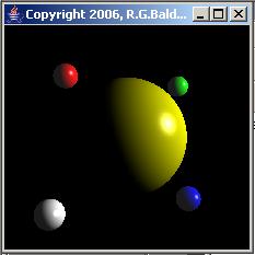
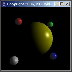
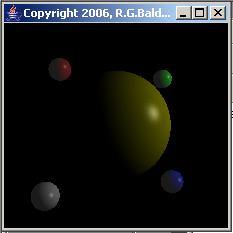
The effects of the two attenuation values that deal with distance are illustrated in Figure 14.
 |
 |
 |
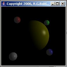 |
Figure 14 | |
The scene properties
The important scene properties for Figure 14 are shown in Table 5.
|
Property |
Case 1 |
Case 2 | Case 3 | Case 4 |
| Facets | 100 | Same as 1 | Same as 1 | Same as 1 |
| Shininess | 128 | Same as 1 | Same as 1 | Same as 1 |
| Diffuse Color | 1.0, 1.0, 0.0 | Same as 1 | Same as 1 | Same as 1 |
| Specular Color | 1.0, 1.0, 1.0 | Same as 1 | Same as 1 | Same as 1 |
| PointLight Color | 1.0, 1.0, 1.0 | Same as 1 | Same as 1 | Same as 1 |
| PointLight Location | 3.0, 1.0, 1.0 | Same as 1 | Same as 1 | Same as 1 |
| PointLight Constant Attenuation | 1.0 | Same as 1 | Same as 1 | Same as 1 |
| PointLight Linear Attenuation | 0.0 | 0.2 | 0.0 | 0.2 |
| PointLight Quadratic Attenuation | 0.0 | 0.0 | 0.2 | 0.2 |
| Table 5 | ||||
The four cases identified by the column headers in Table 5 correspond to the four images in Figure 14, going left to right, top to bottom.
Several scene properties are the same
The top seven properties in Table 5 are the same for all four cases. Only the attenuation values that impact the light intensity as a function of the distance to the source vary among the four cases.
Location of the point-light source
The location of the point-light source is to the right, up, and in front of the centers of all five spheres. That direction is evident from the portion of each of the spheres that is illuminated.
Different attenuation for each image
There is no attenuation of the light intensity as a function of the distance to the light source for the image in the upper-left corner of Figure 14.
The light intensity for the upper-right image is inversely proportional to the distance from each vertex being illuminated to the light source. As you can see, the upper-right image is dimmer than the upper-left image due to this attenuation.
The light intensity for the lower-left image is inversely proportional to the square of the distance from each vertex to the light source. As you can also see, it is somewhat dimmer than the upper-right image.
Finally, the light intensity in the lower-right image is attenuated by both the distance to and the square of the distance to the light source. This image is dimmer than all the others.
Light intensity varies across the scene
Although it may not be apparent, (due mainly to the lack of a reference for comparison), with the exception of the upper-left image, the light intensity decreases going diagonally from right to left and downward across the scenes in Figure 14. This is because of differences in the distance from each of the vertices to the light source, and the attenuation of the light intensity as a function of distance to the light source.
A better example
The attenuation of light intensity as a function of distance to the light source is probably better illustrated by Figure 15, which can be compared to a similar scene in Figure 11 where there is no attenuation of light intensity as a function of distance.
Figure 15 |
The important scene properties for Figure 15 are shown in Table 6.
|
Property |
Property Value |
| Facets | 100 |
| Shininess | 64.0 |
| Diffuse Color | 0.0, 1.0, 1.0 |
| PointLight Color | 1.0, 1.0, 1.0 |
| PointLight Location | 2.0, -2.0, 0.0 |
| PointLight Attenuation | 1.0, 0.0, 0.05 |
| Table 6 | |
The direction of the light source
The direction from the light source to the center of the large sphere is the same in Figure 11 and Figure 15. However, Figure 11 is illuminated by a directional-light source where there is no attenuation in light intensity across the scene. Figure 15 is illuminated by a point-light source where there is attenuation in light intensity across the scene.
The location of the point-light source
The point-light source in Figure 15 is located on a line that goes through the centers of the large sphere and the small red and blue spheres. It is located a little to the right and down from the small blue sphere.
The small blue sphere
The small blue sphere is closest to the light source in both Figure 11 and Figure 15. The light intensity for the small blue sphere was adjusted to be approximately the same for both cases.
Light intensity for the other four spheres
The light intensity for the small red sphere, which is the greatest distance from the light source, is noticeably lower in Figure 15 than in Figure 11. The light intensity for the other three spheres is also lower in Figure 15 than in Figure 11.
Direction from the white and green spheres
Because of the closeness of the light source to the spheres in Figure 15, the direction from the white and green spheres to the light source is considerably different from the direction of the other three spheres to the light source.
If you look carefully, you can see that the area of illumination on the white sphere in Figure 15 is rotated relative to the area of illumination on the white sphere in Figure 11 to take this difference in direction into account. The same is true for the green spheres in the two figures, but because the green spheres are smaller and further away than the white spheres, the effect isn't quite as pronounced.
The scene in Figure 16 is the same as the scene in Figure 15 except that I added white specular reflection capability to the large sphere in Figure 16.
Figure 16 |
In my opinion, the inclusion of specular reflection definitely causes the scene to look more realistic. However, I sometimes get the feeling that the specular reflections don't always properly reflect the angles involved.
Table 7 provides the important scene properties for Figure 16
|
Property |
Property Value |
| Facets | 100 |
| Shininess | 64.0 |
| Specular Color | 1.0, 1.0, 1.0 |
| Diffuse Color | 0.0, 1.0, 1.0 |
| PointLight Color | 1.0, 1.0, 1.0 |
| PointLight Location | 2.0, -2.0, 0.0 |
| PointLight Attenuation | 1.0, 0.0, 0.05 |
| Table 7 | |
Specular reflection behaves pretty much the same regardless of whether the light source is a directional-light source, a point-light source, or a spotlight source.
What is a SpotLight object?
A SpotLight object is like a PointLight object on steroids. As with a point-light source, you can specify the color, location, and attenuation factors for a spotlight source. In addition, instead of being omnidirectional, a spotlight provides a narrow beam of illumination. You can specify three additional properties for a spotlight source, which are used to control the narrow beam.
What does Sun have to say?
According to Sun:
"The SpotLight object specifies an attenuated light source at a fixed point in space that radiates light in a specified direction from the light source. A SpotLight has the same attributes as a PointLight node, with the addition of the following:
- Direction - The axis of the cone of light. The default direction is (0.0, 0.0, -1.0). The spot light direction is significant only when the spread angle is not PI radians (which it is by default).
- Spread angle - The angle in radians between the direction axis and a ray along the edge of the cone. Note that the angle of the cone at the apex is then twice this value. The range of values is [0.0,PI/2] radians, with a special value of PI radians. Values lower than 0 are clamped to 0 and values over PI/2 are clamped to PI. The default spread angle is PI radians.
- Concentration - Specifies how quickly the light intensity attenuates as a function of the angle of radiation as measured from the direction of radiation. The light's intensity is highest at the center of the cone and is attenuated toward the edges of the cone by the cosine of the angle between the direction of the light and the direction from the light to the object being lit, raised to the power of the spot concentration exponent. The higher the concentration value, the more focused the light source. The range of values is [0.0,128.0]. The default concentration is 0.0, which provides uniform light distribution."
Creating a spotlight source
You create a spotlight source for this program by selecting among the five radio buttons beginning with SpotLt Color in Figure 2. You use the first three of the five radio buttons to specify the color, location, and attenuation of the spotlight source (just like a point-light source). You use the button labeled SpotLt Vector to specify the direction of the spotlight. You use the button labeled SpotLt SprCon to specify the spread angle and the concentration.
A spotlight example for progressively wider spread angles
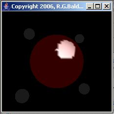
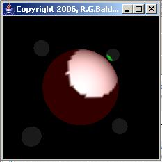
Figure 17 shows a series of four scenes that illustrate the use of a white spotlight source to illuminate a large sphere for progressively wider spread angles on the spotlight.
 |
 |
 |
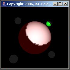 |
Figure 17 | |
The scene properties
The important scene properties for Figure 17 are shown in Table 8.
|
Property |
Case 1 |
Case 2 | Case 3 | Case 4 |
| Facets | 100 | Same as 1 | Same as 1 | Same as 1 |
| Emissive Color | 0.2, 0.0, 0.0 | Same as 1 | Same as 1 | Same as 1 |
| Diffuse Color | 1.0, 1.0, 1.0 | Same as 1 | Same as 1 | Same as 1 |
| SpotLight Color | 1.0, 1.0, 1.0 | Same as 1 | Same as 1 | Same as 1 |
| SpotLight Location | 0.0, 0.0, 4.0 | Same as 1 | Same as 1 | Same as 1 |
| SpotLight Constant Attenuation | 1.0 | Same as 1 | Same as 1 | Same as 1 |
| SpotLight Linear Attenuation | 0.0 | Same as 1 | Same as 1 | Same as 1 |
| SpotLight Quadratic Attenuation | 0.0 | Same as 1 | Same as 1 | Same as 1 |
| SpotLight Vector | 0.4, 0.5, -10.0 | Same as 1 | Same as 1 | Same as 1 |
| SpotLight Spread Angle | 0.04 | 0.06 | 0.08 | 0.10 |
| SpotLight Concentration | 0.0 | Same as 1 | Same as 1 | Same as 1 |
| Table 8 | ||||
The color of the sphere
The diffuse color for the large sphere is white. The sphere was also given a small amount of red emissive color to cause the portion of the sphere not illuminated by the spotlight to be visible (instead of being black).
The spread angle
The allowable range for the spread angle in this program is from 0 to 0.1 radians. The spread angle for this series of four scenes ranges from 0.04 radians in the upper-left image to 0.1 radians in the lower-right image.
As you can see, for the two larger spread angles in the bottom images of Figure 17, the spotlight not only illuminated part of the large sphere, it also spilled over and illuminated part of the small green sphere as well.
Not a smooth outline
Ideally, we would like to see a smooth outline for the area illuminated by a spotlight source. Unfortunately, the outline is not smooth. Rather, the facets on the surface of the sphere cause the outline to be ragged.
The concentration property value
The value for the concentration property was 0.0 for all four scenes in Figure 17, resulting in uniform light intensity across the entire spread angle. Note, however that even though the light intensity is uniform across the illuminated area, Gouraud shading comes into play and the rendered color of the illuminated area is not uniform.
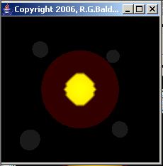
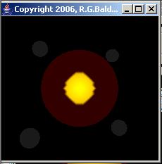
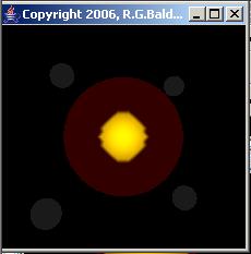
A spotlight example for progressively higher concentration values
Figure 18 shows a series of four scenes that illustrate the use of a white spotlight source to illuminate the large sphere using the maximum spread angle and progressively larger values of the concentration property.
 |
 |
 |
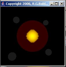 |
Figure 18 | |
(The illuminated area is smaller in Figure 18 than in Figure 17 because the spotlight location was closer to the sphere in Figure 18. As a result, the diameter of the cone of light was smaller at the point where it intersected the surface of the sphere in Figure 18.)
The scene properties
The important scene properties for Figure 18 are shown in Table 9.
|
Property |
Case 1 |
Case 2 | Case 3 | Case 4 |
| Facets | 100 | Same as 1 | Same as 1 | Same as 1 |
| Emissive Color | 0.2, 0.0, 0.0 | Same as 1 | Same as 1 | Same as 1 |
| Diffuse Color | 1.0, 1.0, 0.0 | Same as 1 | Same as 1 | Same as 1 |
| SpotLight Color | 1.0, 1.0, 1.0 | Same as 1 | Same as 1 | Same as 1 |
| SpotLight Location | 0.0, 0.0, 2.0 | Same as 1 | Same as 1 | Same as 1 |
| SpotLight Constant Attenuation | 1.0 | Same as 1 | Same as 1 | Same as 1 |
| SpotLight Linear Attenuation | 0.0 | Same as 1 | Same as 1 | Same as 1 |
| SpotLight Quadratic Attenuation | 0.0 | Same as 1 | Same as 1 | Same as 1 |
| SpotLight Vector | 0.0, 0.0, -10.0 | Same as 1 | Same as 1 | Same as 1 |
| SpotLight Spread Angle | 0.1 | Same as 1 | Same as 1 | Same as 1 |
| SpotLight Concentration | 0.0 | 42.0 | 85.0 | 128.0 |
| Table 9 | ||||
Pointing directly at the center of the sphere
In Figure 17 discussed earlier, the spotlight was used to illuminate a portion of the surface of the large sphere that was off to the right and up relative to the location of the spotlight. However, in Figure 18, the location of the spotlight was directly in front of the large sphere, and the spotlight was pointed at the center of the sphere. As a result, the outline of the illumination area was symmetrical on both the x and y axes, and was generally concentric with the outline of the sphere.
(As mentioned earlier, the actual shape of the illumination area for a spotlight is heavily influenced by the facets on the surface of the sphere.)
The concentration values
The allowable range of concentration values for this program is 0.0 to 128.0.
The concentration value was 0.0 for the image shown in the upper left corner of Figure 18. Thus, the light intensity for this image was uniform across the spread angle of the spotlight. Furthermore, the illumination area was a sufficiently small percentage of the area of the sphere that there was very little effect from Gouraud shading.
The concentration values were increased in three equal steps in order from left to right, top to bottom. This resulted in a concentration value of 128.0 for the image in the lower-right corner of Figure 18.
As you can see, the outer edge of the illuminated area became slightly darker with each increase in the concentration value. However, the effect was not as pronounced as I might have hoped for.
Figure 19 shows a scene that uses a spotlight with maximum spread angle and maximum concentration to illuminate part of a large red sphere and part of the small green sphere that you have seen in numerous previous scenes.
Figure 19 |
The scene properties
The important screen properties for Figure 19 are shown in Table 10.
|
Property |
Property Value |
| Facets | 100 |
| Shininess | 128.0 |
| Emissive Color | 0.3, 0.0, 0.0 |
| Diffuse Color | 1.0, 0.0, 0.0 |
| Specular Color | 1.0, 1.0, 1.0 |
| SpotLight Color | 1.0, 1.0, 1.0 |
| SpotLight Location | 0.2, 0.0, 4.0 |
| SpotLight Constant Attenuation | 1.0 |
| SpotLight Linear Attenuation | 0.0 |
| SpotLight Quadratic Attenuation | 0.0 |
| SpotLight Vector | 0.0, 0.5, -10.0 |
| SpotLight Spread Angle | 0.1 |
| SpotLight Concentration | 128.0 |
| Table 10 | |
Both the green sphere and the red sphere have a white specular color. As you can see, the white spotlight produces a white specular reflection on both spheres.
Changing the concentration value
The green sphere is at the outer edge of the spread angle for the spotlight. Thus, the illumination of the green sphere in Figure 19 is strongly influenced by the high concentration property value.
Figure 20 shows the results of rerunning this case with the concentration property value set to 0.0.
Figure 20 |
As you can see, the illumination of the green sphere is noticeably brighter in Figure 20 as compared to Figure 19 when the concentration value has been modified to produce uniform light intensity across the entire spread angle.
I encourage you to copy the code from Listing 1 into your text editor, compile it, and execute it. Use the graphical user interface to experiment with the many features of Java 3D lighting to improve your understanding of those features.
Experiment with the code, making changes, and observing the results of your changes. For example, you might want to consider replacing one or more of the spheres with other 3D shapes such as cones or cubes to see what impact those changes have on the 3D scene lighting.
In order to compile and run this program, you must download and install the Java 3D API. As of the date of this writing, it was available at: http://java.sun.com/products/java-media/3D/. The online documentation was available at: http://download.java.net/media/java3d/javadoc/1.4.0/.
In addition, you must download and install either Microsoft DirectX or OpenGL.
In this lesson, I taught you about, and showed you examples of many of the important features of scene illumination in the Java 3D API. I also provided the source code for a complete Java 3D lighting simulator that you can compile and run to experiment with light in the Java 3D API.
I will explain how the Java 3D lighting simulator program works in subsequent parts of this multi-part lesson.
Several important references related to the rendering of 3D light are listed below:
A complete listing of the program discussed in this lesson is provided in Listing 1.
/*File Lighting3D04.java
Copyright 2006, R.G.Baldwin
This Java 3D lighting simulator program can be used to
exercise most of the lighting and illumination features of
the Java 3D API either individually or in combination with
one another.
In order to compile and run this program, you must download
and install the Java 3D API. As of the date of this
writing, it was available at:
http://java.sun.com/products/java-media/3D/
The online documentation was available at:
http://download.java.net/media/java3d/javadoc/1.4.0/
You must also have either Microsoft DirectX or OpenGL
installed on your computer.
See http://www.microsoft.com/windows/directx/default.mspx
or http://www.opengl.org/
The comments in the body of the program contain numerous
references to Chapter 6 of a document published by
Dennis J. Bouvier at the following URL.
http://java.sun.com/developer/onlineTraining/java3d/
j3d_tutorial_ch6.pdf
In most cases, the references are cited by page or section
number.
Here is an example of the type of material provided by
Bouvier: "In the real world, the colors we perceive are a
combination of the physical properties of the object, the
characteristics of the light sources, the objects' relative
positions to light sources, and the angle from which the
object is viewed. Java 3D uses a lighting model to
approximate the physics of the real world."
According to Bouvier, Section E.2 of The Java 3D API
Specification presents the mathematical equations of the
Java 3D lighting model. As of the date of this writing,
the specification can be found at:
http://java.sun.com/products/java-media/3D/forDevelopers/
j3dguide/j3dTOC.doc.html
Still quoting Bouvier, "The lighting model equation depends
on three vectors: the surface normal (N), the light
direction (L), and the direction to the viewer's eye (E) in
addition to the Material properties of the object and the
light characteristics."
This program makes it easy for the user to vary the surface
normal (indirectly), the light direction, and the Material
properties of the object. The program does not make it
possible for the user to easily modify the direction to the
viewer's eye. However, the primary experimental object is
a large sphere which, because of its curvature, inherently
results in a wide range of directions from the object to
the user's eye.
Back to Bouvier, "The lighting model incorporates three
kinds of real world lighting reflections: ambient, diffuse,
and specular. Ambient reflection results from AmbientLight,
constant low level light, in a scene. Diffuse reflection is
the normal reflection of a light source from a visual
object. Specular reflections are the highlight reflections
of a light source from an object, which occur in certain
situations."
This program produces two user interfaces. One interface
is the display of a 3D scene containing five spheres.
Four of the spheres are small with fixed reflective
surface properties and a fixed number of facets. When
illuminated with either white light or light having a color
that matches the reflective color of the sphere, these
small spheres appear as white, red, green, and blue.
The fifth sphere is larger, and almost everything about
this sphere other than its size and location can be
modified by the user through the second user interface.
This makes it possible for the user to view the effects of
those modifications in conjunction with varying light
conditions. For example, the user can control almost all
aspects of the following characteristics of the large
sphere:
The number of facets on the surface of the sphere.
The shininess of the sphere.
The emissive color and intensity.
The ambient color and intensity.
The diffuse color and intensity.
The specular color and intensity.
The type of shading: gouraud shading or flat shading.
In addition, the user has control over the following lights
and their characteristics of color, intensity, direction,
location, attenuation, spreading, and concentration as
applicable:
One AmbientLight object.
Two independent DirectionalLight objects.
One PointLight object.
One SpotLight object.
For example, having specified the various properties of
the large sphere, the user can vary the properties of the
lights and observe the manner in which the lights interract
with the five spheres to illuminate the scene.
The properties of the large sphere and the lights are
varied by selecting a radio button that corresponds
to the property and then adjusting three sliders. The
display of the scene changes as the user adjusts the
sliders, making it possible to easily view the effects of
fixing all properties but one and then varying that
property across a range of values.
The second user interface also makes it possible for the
user to select between a large and a small display. This
was done primarily to support my publishing efforts when
I publish a tutorial lesson explaining this program.
Tested using J2SE 5.0, the Java 3D API v1.4.0, WinXP,
and the version of DirectX published by Microsoft in
April, 2006. The program was not tested with OpenGL.
**********************************************************/
import com.sun.j3d.utils.universe.SimpleUniverse;
import com.sun.j3d.utils.geometry.Sphere;
import com.sun.j3d.utils.geometry.Primitive;
import javax.media.j3d.BranchGroup;
import javax.media.j3d.ColoringAttributes;
import javax.media.j3d.Canvas3D;
import javax.media.j3d.Material;
import javax.media.j3d.Appearance;
import javax.media.j3d.BoundingSphere;
import javax.media.j3d.AmbientLight;
import javax.media.j3d.DirectionalLight;
import javax.media.j3d.PointLight;
import javax.media.j3d.SpotLight;
import javax.media.j3d.Transform3D;
import javax.media.j3d.TransformGroup;
import javax.media.j3d.Locale;
import javax.vecmath.Point3d;
import javax.vecmath.Point3f;
import javax.vecmath.Color3f;
import javax.vecmath.Vector3f;
import java.awt.Frame;
import java.awt.Panel;
import java.awt.Label;
import java.awt.Dimension;
import java.awt.TextField;
import java.awt.BorderLayout;
import java.awt.GraphicsConfiguration;
import java.awt.GridLayout;
import java.awt.event.ActionListener;
import java.awt.event.ActionEvent;
import java.awt.event.WindowAdapter;
import java.awt.event.WindowEvent;
import javax.swing.Timer;
import javax.swing.JSlider;
import javax.swing.JRadioButton;
import javax.swing.ButtonGroup;
import javax.swing.event.ChangeListener;
import javax.swing.event.ChangeEvent;
public class Lighting3D04 extends Frame
implements ActionListener{
//The scene is rendered periodically on the basis of
// timer events. The following flag is used to avoid
// rendering the scene when it hasn't changed since the
// last time it was rendered.
boolean sceneHasChanged = true;
static Timer timer;//Used to update the scene image.
ControlPanel controlPanel;
SliderPanel sliderPanel;
JSlider topSlider;
JSlider middleSlider;
JSlider bottomSlider;
Label topSliderLabel = new Label("",Label.CENTER);
Label middleSliderLabel = new Label("",Label.CENTER);
Label bottomSliderLabel = new Label("",Label.CENTER);
Label column1;//Column headers
Label column2;
Label column3;
Dimension largeDisplaySize = new Dimension(472,472);
Dimension smallDisplaySize = new Dimension(232,232);
//Ref to the main graphic display.
Lighting3D04 displayObject;
//Default value at startup and max value
int facets = 100;
float shininess = 64.0f;//Default value at startup
//Default shading is Gouraud. Alternate is SHADE_FLAT.
// Modified when user selects a shading button.
int shading = ColoringAttributes.SHADE_GOURAUD;
//The following constant specifies the number of radio
// buttons on the control panel. This is also the number
// of items whose values can be adjusted by the user.
final int numRadioButtons = 19;
//The following array contains the parameter values used
// to specify the scene. The rows in the array
// correspond to the following items:
// 0 Facets - Used to construct sphere0. This is the
// number of flats encountered in one pass around the
// equator of the sphere.
// 1 Shininess - A property of the Material that
// comprises the surface of sphere0.
// 2 Emissive color - The color of the light emitted by
// sphere0 in the absence of a light source.
// 3 Ambient color - The color of the surface of sphere0
// in the presence of AmbientLight.
// 4 Diffuse color - The color of the surface of sphere0
// resulting from being illuminated with
// DirectionalLight, PointLight, or SpotLight.
// 5 Specular color - The color of the highlights on the
// surface of sphere0 when illuminated with
// DirectionalLight, PointLight, or SpotLight.
// 6 AmbientLight - The color and intensity of
// non-directional AmbientLight. Interacts only with
// ambient color described above.
// 7 DirectionalLight 1 - The color and intensity of a
// DirectionalLight.
// 8 DirectionalLight 1 vector - A vector that specifies
// the direction.
// 9 DirectionalLight 2 - The color and intensity of a
// second DirectionalLight.
//10 DirectionalLight 2 vector - A vector that specifies
// the direction
//11 PointLight - The color and intensity of a
// PointLight.
//12 PointLight location - The location of the
// PointLight.
//13 PointLight attenuation - Attenuation values for the
// PointLight.
//14 SpotLight - The color and intensity of a SpotLight.
//15 SpotLight location - The location of the SpotLight.
//16 SpotLight attenuation - Attenuation values for the
// SpotLight
//17 SpotLight vector - A vector that specifies the
// direction
//18 SpotLight spreading and concentration factors.
float[][] data = new float[numRadioButtons][3];
//An array containing references to a group of radio
// buttons.
JRadioButton[] radioButtonArray =
new JRadioButton[numRadioButtons];
//References to objects that are peculiar to the Java 3D
// API.
BranchGroup scene;
SimpleUniverse universe;
//-----------------------------------------------------//
public static void main(String[] args){
new Lighting3D04();
//Start the timer that will cause the display to be
// updated periodically.
timer.start();
}//end main
//-----------------------------------------------------//
public Lighting3D04(){//constructor
//The controller contains the sliderPanel, the
// controlPanel, and the buttonPanel.
Frame controller =
new Frame("Copyright 2006, R.G.Baldwin");
controller.setBounds(473,0,472,718);
controller.addWindowListener(
new WindowAdapter(){
public void windowClosing(WindowEvent e){
System.exit(0);
}//end windowClosing
}//end new WindowAdapter
);//end addWindowListener
//The controlPanel contains radio buttons and text
// fields in the CENTER of the controller.
controlPanel = new ControlPanel();
controller.add(controlPanel,BorderLayout.CENTER);
//The sliderPanel contains sliders in the NORTH of the
// controller
sliderPanel = new SliderPanel();
controller.add(sliderPanel,BorderLayout.NORTH);
//The buttonPanel contains radio buttons in the SOUTH
// of the controller.
ButtonPanel buttonPanel = new ButtonPanel();
controller.add(buttonPanel,BorderLayout.SOUTH);
controller.setVisible(true);
//Create the timer that will be used to periodically
// update the display.
timer = new Timer(200,this);
//Construct the 3D display
GraphicsConfiguration config =
SimpleUniverse.getPreferredConfiguration();
Canvas3D canvas = new Canvas3D(config);
add("Center", canvas);
//Create a scene and attach it to the virtual universe
scene = createSceneGraph();
universe = new SimpleUniverse(canvas);
universe.getViewingPlatform().
setNominalViewingTransform();
universe.addBranchGraph(scene);
setSize(largeDisplaySize);//default to large display
setTitle("Copyright 2006, R.G.Baldwin");
setVisible(true);
//Save a reference to the display object so that other
// methods can access it.
displayObject = this;
addWindowListener(
new WindowAdapter(){
public void windowClosing(WindowEvent e){
System.exit(0);
}//end windowClosing
}//end new WindowAdapter
);//end addWindowListener
}//end constructor
//-----------------------------------------------------//
//This method is called to create the scene.
public BranchGroup createSceneGraph(){
// Create the root of the branch graph
BranchGroup objRoot = new BranchGroup();
//Create sphere0
//See http://java.sun.com/developer/onlineTraining/
// java3d/j3d_tutorial_ch6.pdf, page 6-21 re Material
Material sphere0Surface = new Material();
//The shininess value is only used in calculating
// specular reflections. The shininess value controls
// the spread range of viewing angle for which a
// specular reflection can be seen. Higher shininess
// values result in smaller specular reflections. See
// page 6-23
sphere0Surface.setShininess(data[1][0]);
sphere0Surface.setEmissiveColor(
data[2][0],data[2][1],data[2][2]);
sphere0Surface.setAmbientColor(
data[3][0],data[3][1],data[3][2]);
sphere0Surface.setDiffuseColor(
data[4][0],data[4][1],data[4][2]);
//When a surface is sufficiently smooth, it acts like a
// mirror reflecting the light without changing the
// color of the light. Consequently, the specular color
// of an object is normally white. See page 6-22.
sphere0Surface.setSpecularColor(
data[5][0],data[5][1],data[5][2]);
Appearance appearance0 = new Appearance();
appearance0.setMaterial(sphere0Surface);
//Specify SHADE_GOURAUD or SHADE_FLAT shading.
ColoringAttributes coloringAttributes =
new ColoringAttributes();
coloringAttributes.setShadeModel(shading);
appearance0.setColoringAttributes(coloringAttributes);
//Construct the large sphere. See page 6-4 and
// page 6-24 re NORMALS.
Sphere sphere0 = new Sphere(0.48f,
Primitive.GENERATE_NORMALS,
(int)(data[0][0]),
appearance0);
//Now construct four small spheres with fixed surface
// properties and a fixed number of facets. Shading
// depends on the value stored in coloringAttributes
// that was constructed above.
//Construct a small white calibration sphere located
// down to the left and closer than the main sphere.
Material sphere1Surface = new Material();
sphere1Surface.setShininess(128.0f);
sphere1Surface.setEmissiveColor(0.1f,0.1f,0.1f);
sphere1Surface.setAmbientColor(1.0f,1.0f,1.0f);
sphere1Surface.setDiffuseColor(1.0f,1.0f,1.0f);
sphere1Surface.setSpecularColor(1.0f,1.0f,1.0f);
Appearance appearance1 = new Appearance();
appearance1.setMaterial(sphere1Surface);
appearance1.setColoringAttributes(coloringAttributes);
Sphere sphere1 = new Sphere(0.10f,
Primitive.GENERATE_NORMALS,
50,
appearance1);
Transform3D position1 = new Transform3D();
position1.setTranslation(
new Vector3f(-0.5f,-0.5f,0.5f));
TransformGroup objTrans1 = new TransformGroup();
objTrans1.setCapability(
TransformGroup.ALLOW_TRANSFORM_WRITE);
objTrans1.setTransform(position1);
objTrans1.addChild(sphere1);
//Construct a small red sphere located up to the left
// and in the same z-plane as the large sphere.
Material sphere2Surface = new Material();
sphere2Surface.setShininess(128.0f);
sphere2Surface.setEmissiveColor(0.1f,0.1f,0.1f);
sphere2Surface.setAmbientColor(1.0f,0.0f,0.0f);
sphere2Surface.setDiffuseColor(1.0f,0.0f,0.0f);
sphere2Surface.setSpecularColor(1.0f,1.0f,1.0f);
Appearance appearance2 = new Appearance();
appearance2.setMaterial(sphere2Surface);
appearance2.setColoringAttributes(coloringAttributes);
Sphere sphere2 = new Sphere(0.10f,
Primitive.GENERATE_NORMALS,
50,
appearance2);
Transform3D position2 = new Transform3D();
position2.setTranslation(
new Vector3f(-0.5f,0.5f,0.0f));
TransformGroup objTrans2 = new TransformGroup();
objTrans2.setCapability(
TransformGroup.ALLOW_TRANSFORM_WRITE);
objTrans2.setTransform(position2);
objTrans2.addChild(sphere2);
//Construct a small green sphere located up to the
// right and behind the large sphere.
Material sphere3Surface = new Material();
sphere3Surface.setShininess(128.0f);
sphere3Surface.setEmissiveColor(0.1f,0.1f,0.1f);
sphere3Surface.setAmbientColor(0.0f,1.0f,0.0f);
sphere3Surface.setDiffuseColor(0.0f,1.0f,0.0f);
sphere3Surface.setSpecularColor(1.0f,1.0f,1.0f);
Appearance appearance3 = new Appearance();
appearance3.setMaterial(sphere3Surface);
appearance3.setColoringAttributes(coloringAttributes);
Sphere sphere3 = new Sphere(0.10f,
Primitive.GENERATE_NORMALS,
50,
appearance3);
Transform3D position3 = new Transform3D();
position3.setTranslation(
new Vector3f(0.5f,0.5f,-0.5f));
TransformGroup objTrans3 = new TransformGroup();
objTrans3.setCapability(
TransformGroup.ALLOW_TRANSFORM_WRITE);
objTrans3.setTransform(position3);
objTrans3.addChild(sphere3);
//Constructa small blue sphere located down to the
// right and in the same z-plane as the large sphere.
Material sphere4Surface = new Material();
sphere4Surface.setShininess(128.0f);
sphere4Surface.setEmissiveColor(0.1f,0.1f,0.1f);
sphere4Surface.setAmbientColor(0.0f,0.0f,1.0f);
sphere4Surface.setDiffuseColor(0.0f,0.0f,1.0f);
sphere4Surface.setSpecularColor(1.0f,1.0f,1.0f);
Appearance appearance4 = new Appearance();
appearance4.setMaterial(sphere4Surface);
appearance4.setColoringAttributes(coloringAttributes);
Sphere sphere4 = new Sphere(0.10f,
Primitive.GENERATE_NORMALS,
50,
appearance4);
Transform3D position4 = new Transform3D();
position4.setTranslation(
new Vector3f(0.5f,-0.5f,-0.0f));
TransformGroup objTrans4 = new TransformGroup();
objTrans4.setCapability(
TransformGroup.ALLOW_TRANSFORM_WRITE);
objTrans4.setTransform(position4);
objTrans4.addChild(sphere4);
//See page 6-3 and page 6-25 re BoundingSphere.
BoundingSphere boundingSphere =
new BoundingSphere(new Point3d(0.0,0.0,0.0), 1.0);
//Now add the lights to the scene. See page 6-11
// and page 6-13. DirectionalLights only participate
// in diffuse and specular reflection portions of the
// lighting model. For diffuse and specular
// reflections, the geometry is a factor (unlike
// ambient reflections). Varying the direction of the
// light source will change the shading of visual
// objects. Only diffuse and specular Material
// properties are used in calculating the diffuse and
// specular reflections. Section 6-4 presents Material
// properties of visual objects in more detail.
//Add an AmbientLight. Requires an ambient reflection
// component on a surface to be visible.
Color3f light0Color =
new Color3f(data[6][0],data[6][1],data[6][2]);
AmbientLight light0 =
new AmbientLight(true,light0Color);
light0.setInfluencingBounds(boundingSphere);
//Add a DirectionalLight.
Color3f light1Color =
new Color3f(data[7][0],data[7][1],data[7][2]);
Vector3f light1Direction =
new Vector3f(data[8][0],data[8][1],data[8][2]);
DirectionalLight light1 =
new DirectionalLight(light1Color, light1Direction);
light1.setInfluencingBounds(boundingSphere);
//Add another DirectionalLight
Color3f light2Color =
new Color3f(data[9][0],data[9][1],data[9][2]);
Vector3f light2Direction =
new Vector3f(data[10][0],data[10][1],data[10][2]);
DirectionalLight light2 =
new DirectionalLight(light2Color, light2Direction);
light2.setInfluencingBounds(boundingSphere);
//Add a PointLight. See pages 6-13 and 6-14. Like a
// DirectionalLight, a PointLight only participates
// in diffuse and specular reflection portions of the
// lighting model. For diffuse and specular
// reflections, the geometry is a factor. Varying the
// location of a PointLight object will change the
// shading of visual objects in a scene.
Color3f light3Color =
new Color3f(data[11][0],data[11][1],data[11][2]);
Point3f light3Position =
new Point3f(data[12][0],data[12][1],data[12][2]);
Point3f light3Attenuation =
new Point3f(data[13][0],data[13][1],data[13][2]);
PointLight light3 = new PointLight(light3Color,
light3Position,
light3Attenuation);
light3.setInfluencingBounds(boundingSphere);
//Add a SpotLight
Color3f light4Color =
new Color3f(data[14][0],data[14][1],data[14][2]);
Point3f light4Position =
new Point3f(data[15][0],data[15][1],data[15][2]);
Point3f light4Attenuation =
new Point3f(data[16][0],data[16][1],data[16][2]);
Vector3f light4Direction =
new Vector3f(data[17][0],data[17][1],data[17][2]);
float light4Spread = data[18][0];
float light4Concentration = data[18][1];
SpotLight light4 = new SpotLight(light4Color,
light4Position,
light4Attenuation,
light4Direction,
light4Spread,
light4Concentration);
light4.setInfluencingBounds(boundingSphere);
//Now add all of the spheres and the lights to the
// scene.
objRoot.addChild(sphere0);
objRoot.addChild(objTrans1);
objRoot.addChild(objTrans2);
objRoot.addChild(objTrans3);
objRoot.addChild(objTrans4);
objRoot.addChild(light0);
objRoot.addChild(light1);
objRoot.addChild(light2);
objRoot.addChild(light3);
objRoot.addChild(light4);
//The following statement makes it possible for the
// event handler on the timer to remove the current
// scene and to replace it with a new scene constructed
// using different parameters.
objRoot.setCapability(BranchGroup.ALLOW_DETACH);
return objRoot;
}//end createSceneGraph
//-----------------------------------------------------//
//This ActionListener services the timer events. Each
// time it is notified, it checks to see if the scene
// has changed since the previous call. If the scene has
// changed, it removes the current scene and creates a
// new one using new parameter values. If the scene
// hasn't changed, it does not create a new scene.
public void actionPerformed(ActionEvent e){
if(sceneHasChanged){
//Set the flag to false to avoid rendering it on the
// next timer event unless it has changed in the
// meantime.
sceneHasChanged = false;
//Go ahead and render the scene because it has
// changed since the last time that it was rendered.
Locale locale = universe.getLocale();
locale.removeBranchGraph(scene);
scene = createSceneGraph();
locale.addBranchGraph(scene);
}//end if
}//end actionPerformed
//-----------------------------------------------------//
//An object of this inner class is placed in the SOUTH
// location of the controller. It provides radio buttons
// for selection of the type of shading, Gouraud or Flat.
// It also provides radio buttons for selection of the
// display size, large or small.
class ButtonPanel extends Panel{
ButtonPanel(){//constructor
setLayout(new GridLayout(0,2));
JRadioButton gouraudButton =
new JRadioButton("Gouraud Shading",true);
JRadioButton flatButton =
new JRadioButton("Flat Shading");
ButtonGroup shadingGroup = new ButtonGroup();
shadingGroup.add(gouraudButton);
shadingGroup.add(flatButton);
//Register action listeners on the buttons to provide
// the appropriate behavior when they are selected.
gouraudButton.addActionListener(
new ActionListener(){
public void actionPerformed(ActionEvent e){
shading = ColoringAttributes.SHADE_GOURAUD;
//Cause the scene to be rendered on the next
// timer event.
sceneHasChanged = true;
}//end actionPerformed
}//end new ActionListener
);//end addActionListener
flatButton.addActionListener(
new ActionListener(){
public void actionPerformed(ActionEvent e){
shading = ColoringAttributes.SHADE_FLAT;
//Cause the scene to be rendered on the next
// timer event.
sceneHasChanged = true;
}//end actionPerformed
}//end new ActionListener
);//end addActionListener
JRadioButton largeDisplay =
new JRadioButton("Large Display",true);
JRadioButton smallDisplay =
new JRadioButton("Small Display");
ButtonGroup displaySizeGroup = new ButtonGroup();
displaySizeGroup.add(largeDisplay);
displaySizeGroup.add(smallDisplay);
//Register action listeners on the buttons to provide
// the appropriate behavior when they are selected.
largeDisplay.addActionListener(
new ActionListener(){
public void actionPerformed(ActionEvent e){
displayObject.setSize(largeDisplaySize);
//Cause the scene to be rendered on the next
// timer event.
sceneHasChanged = true;
}//end actionPerformed
}//end new ActionListener
);//end addActionListener
smallDisplay.addActionListener(
new ActionListener(){
public void actionPerformed(ActionEvent e){
displayObject.setSize(smallDisplaySize);
//Cause the scene to be rendered on the next
// timer event.
sceneHasChanged = true;
}//end actionPerformed
}//end new ActionListener
);//end addActionListener
//Populate the grid from left to right, top to
// bottom to arrange the radio buttons in the panel.
add(gouraudButton);
add(largeDisplay);
add(flatButton);
add(smallDisplay);
}//end constructor
}//end class ButtonPanel
//-----------------------------------------------------//
//An object of this inner class is located in the CENTER
// of the main controller. It provides radio buttons
// along with text fields for selection of the scene
// parameters to be changed and to display the current
// or changed values of those parameters.
class ControlPanel extends Panel
implements ActionListener{
//The text fields used to display the scene property
// values are arranged in a grid having three columns
// and numRadioButtons rows. Each of the following
// arrays contains references to the text field
// objects in one column, beginning with the left-most
// column.
TextField[] textFieldCol1 =
new TextField[numRadioButtons];
TextField[] textFieldCol2 =
new TextField[numRadioButtons];
TextField[] textFieldCol3 =
new TextField[numRadioButtons];
//---------------------------------------------------//
//This method is called whenever the user moves an
// enabled slider. The incoming parameters specify
// the slider that was moved and the new value of the
// slider.
void sliderChangeNotification(int slider,int value){
//Determine which radio button was selected when the
// slider was moved. The new value of the slider
// must be associated with the property specified by
// that radio button.
int button = getSelectedButton();
//The following logic uses the radio button
// identification along with the slider
// identification to take the appropriate action for
// a given combination of button and slider.
if((button == 0)&&(slider == 0)){//facets
if(value < 4)value = 4;//clamp at 4
//Display the new slider value in the text field.
textFieldCol1[button].setText("" + value);
//Record the new slider value in the data array.
data[button][0] = value;
}else if((button == 1)&&(slider == 0)){//shininess
textFieldCol1[button].setText("" + (float)(value));
data[button][0] = (float)(value);
//The following buttons generally correspond to scene
// parameters that involve location coordinates,
// such as directional vectors or the location of a
// PointLight. The scale factors used in this logic
// support coordinate values from -10.0 to +10.0 in
// steps of 0.1.
}else if(((button == 8)&&(slider == 0)) ||
((button == 10)&&(slider == 0))||
((button == 12)&&(slider == 0))||
((button == 15)&&(slider == 0))||
((button == 17)&&(slider == 0))){
textFieldCol1[button].setText(
"" + (float)(value/10.0));
data[button][0] = (float)(value/10.0);
}else if(((button == 8)&&(slider == 1)) ||
((button == 10)&&(slider == 1))||
((button == 12)&&(slider == 1))||
((button == 15)&&(slider == 1))||
((button == 17)&&(slider == 1))){
textFieldCol2[button].setText(
"" + (float)(value/10.0));
data[button][1] = (float)(value/10.0);
}else if(((button == 8)&&(slider == 2)) ||
((button == 10)&&(slider == 2))||
((button == 12)&&(slider == 2))||
((button == 15)&&(slider == 2))||
((button == 17)&&(slider == 2))){
textFieldCol3[button].setText(
"" + (float)(value/10.0));
data[button][2] = (float)(value/10.0);
//The following buttons correspond to attenuation
// values for PointLight and SpotLight. The constant
// attenuation value is allowed to vary from 1.0 to
// 2.0 in steps of 0.1. The other two attenuation
// values are allowed to vary from 0.0 to 0.2 in
// steps of 0.01.
}else if(((button == 13)&&(slider == 0))||
((button == 16)&&(slider == 0))){
textFieldCol1[button].setText(
"" + (float)(value/10.0));
data[button][0] = (float)(value/10.0);
}else if(((button == 13)&&(slider == 1))||
((button == 16)&&(slider == 1))){
textFieldCol2[button].setText(
"" + (float)(value/100.0));
data[button][1] = (float)(value/100.0);
}else if(((button == 13)&&(slider == 2))||
((button == 16)&&(slider == 2))){
textFieldCol3[button].setText(
"" + (float)(value/100.0));
data[button][2] = (float)(value/100.0);
//The following button corresponds to SpotLight
// spread angle and SpotLight concentration. Spread
// angle is allowed to vary from 0.0 to 0.1 radian in
// steps of 0.01 radian. Concentration varies from
// 0 to 128 in integer steps of 1.
}else if((button == 18)&&(slider == 0)){
//SpotLight spread angle
textFieldCol1[button].setText(
"" + (float)(value/100.0));
data[button][0] = (float)(value/100.0);
}else if((button == 18)&&(slider == 1)){
//SpotLight concentration
textFieldCol2[button].setText(
"" + (float)(value));
data[button][1] = (float)(value);
//Process all remaining buttons alike. Buttons
// 2,3,4,5,6,7,9,11, and 14 correspond to scene
// properties requiring values for the colors red,
// green, and blue. These values are allowed to
// vary from 0.0 to 1.0 in steps of 0.01.
}else if(slider%3 == 0){
textFieldCol1[button].setText(
"" + (float)(value/100.0));
data[button][0] = (float)(value/100.0);
}else if(slider%3 == 1){
textFieldCol2[button].setText(
"" + (float)(value/100.0));
data[button][1] = (float)(value/100.0);
}else{
textFieldCol3[button].setText(
"" + (float)(value/100.0));
data[button][2] = (float)(value/100.0);
}//end else
//Cause the scene to be rendered on the next timer
// event.
sceneHasChanged = true;
}//end sliderChangeNotification
//---------------------------------------------------//
//This action listener is registered on the large group
// of radio buttons. When a radio button is selected,
// this action listener causes the appropriate action
// to be taken.
public void actionPerformed(ActionEvent e){
int theButton = getSelectedButton();
//Need to save and restore these values because
// they get corrupted when the slider parameters are
// changed.
float buttonData0 = data[theButton][0];
float buttonData1 = data[theButton][1];
float buttonData2 = data[theButton][2];
//This button corresponds to the number of facets on
// the surface of the large sphere. This is allowed
// to range from 4 to 100. Spheres with fewer than 4
// facets don't make much sense so they are not
// allowed
if(theButton == 0){//facets
//Set the range on the slider for facets.
topSlider.setMinimum(0);
topSlider.setMaximum(facets);
//Restore the data value saved above.
data[theButton][0] = buttonData0;
//Cause the slider to be positioned at the current
// data value.
topSlider.setValue((int)(data[theButton][0]));
//Set the labels above the sliders.
topSliderLabel.setText(
"Facets on Surface of Large Sphere");
middleSliderLabel.setText("Disabled");
bottomSliderLabel.setText("Disabled");
//Enable and disable sliders as needed.
topSlider.setEnabled(true);
middleSlider.setEnabled(false);
bottomSlider.setEnabled(false);
//Remove tick marks from disabled sliders.
middleSlider.setMinimum(0);
middleSlider.setMaximum(0);
bottomSlider.setMinimum(0);
bottomSlider.setMaximum(0);
//Set the column headers to match the selected
// radio button.
column1.setText("Facets");
column2.setText("Not Used");
column3.setText("Not Used");
//This button corresponds to shininess. It is
// allowed to range from 0 to 128 integer.
}else if(theButton == 1){
topSlider.setMinimum(0);
topSlider.setMaximum(128);
data[theButton][0] = buttonData0;//restore
topSlider.setValue((int)(data[theButton][0]));
topSliderLabel.setText(
"Shininess of Surface of Large Sphere");
middleSliderLabel.setText("Disabled");
bottomSliderLabel.setText("Disabled");
topSlider.setEnabled(true);
middleSlider.setEnabled(false);
bottomSlider.setEnabled(false);
middleSlider.setMinimum(0);
middleSlider.setMaximum(0);
bottomSlider.setMinimum(0);
bottomSlider.setMaximum(0);
column1.setText("Shininess");
column2.setText("Not Used");
column3.setText("Not Used");
//These buttons correspond to scene properties
// involving color values for red, green, and blue.
}else if((theButton == 2) ||
(theButton == 3) ||
(theButton == 4) ||
(theButton == 5) ||
(theButton == 6) ||
(theButton == 7) ||
(theButton == 9) ||
(theButton == 11) ||
(theButton == 14)){
topSlider.setEnabled(true);
middleSlider.setEnabled(true);
bottomSlider.setEnabled(true);
topSlider.setMinimum(0);
topSlider.setMaximum(100);
middleSlider.setMinimum(0);
middleSlider.setMaximum(100);
bottomSlider.setMinimum(0);
bottomSlider.setMaximum(100);
data[theButton][0] = buttonData0;//restore
data[theButton][1] = buttonData1;//restore
data[theButton][2] = buttonData2;//restore
topSlider.setValue((int)(100*data[theButton][0]));
middleSlider.setValue(
(int)(100*data[theButton][1]));
bottomSlider.setValue(
(int)(100*data[theButton][2]));
topSliderLabel.setText(
"Red Color Component * 100");
middleSliderLabel.setText(
"Green Color Component * 100");
bottomSliderLabel.setText(
"Blue Color Component * 100");
column1.setText("Red Color");
column2.setText("Green Color");
column3.setText("Blue Color");
//These buttons correspond to scene properties
// involving location coordinate values.
}else if((theButton == 8) ||
(theButton == 10)||
(theButton == 12)||
(theButton == 15)||
(theButton == 17)){
topSlider.setEnabled(true);
middleSlider.setEnabled(true);
bottomSlider.setEnabled(true);
topSlider.setMinimum(-100);
topSlider.setMaximum(100);
middleSlider.setMinimum(-100);
middleSlider.setMaximum(100);
bottomSlider.setMinimum(-100);
bottomSlider.setMaximum(100);
data[theButton][0] = buttonData0;//restore
data[theButton][1] = buttonData1;//restore
data[theButton][2] = buttonData2;//restore
topSlider.setValue((int)(10*data[theButton][0]));
middleSlider.setValue(
(int)(10*data[theButton][1]));
bottomSlider.setValue(
(int)(10*data[theButton][2]));
topSliderLabel.setText("X-Coordinate * 10");
middleSliderLabel.setText("Y-Coordinate * 10");
bottomSliderLabel.setText("Z-Coordinate * 10");
column1.setText("X-Coordinate");
column2.setText("Y-Coordinate");
column3.setText("Z-Coordinate");
//These buttons correspond to attenuation values for
// PointLight and SpotLight objects.
}else if((theButton == 13) ||
(theButton == 16)){
topSlider.setEnabled(true);
middleSlider.setEnabled(true);
bottomSlider.setEnabled(true);
topSlider.setMinimum(10);
topSlider.setMaximum(20);
middleSlider.setMinimum(0);
middleSlider.setMaximum(20);
bottomSlider.setMinimum(0);
bottomSlider.setMaximum(20);
data[theButton][0] = buttonData0;//restore
data[theButton][1] = buttonData1;//restore
data[theButton][2] = buttonData2;//restore
//This constant attenuation value ends up being
// used in the denominator of an attenuation
// calculation. If it is less than 1.0, it results
// in a gain instead of an attenuation. This
// doesn't make sense, so it is clamped at 1.0 to
// avoid having a gain and also to avoid division
// by 0.
if(data[theButton][0] < 1.0f){
data[theButton][0] = 1.0f;
}//end if
topSlider.setValue((int)(10*data[theButton][0]));
middleSlider.setValue(
(int)(100*data[theButton][1]));
bottomSlider.setValue(
(int)(100*data[theButton][2]));
topSliderLabel.setText(
"Constant Attenuation * 10");
middleSliderLabel.setText(
"Linear Attenuation * 100");
bottomSliderLabel.setText(
"Quadratic Attenuation * 100");
column1.setText("ConstantAttenuation");
column2.setText("LinearAttenuation");
column3.setText("QuadraticAttenuation");
//This button corresponds to SpotLight spread antle
// and concentration.
}else if(theButton == 18){
topSlider.setEnabled(true);
middleSlider.setEnabled(true);
bottomSlider.setEnabled(false);
topSlider.setMinimum(0);
topSlider.setMaximum(10);
middleSlider.setMinimum(0);
middleSlider.setMaximum(128);
bottomSlider.setMinimum(0);
bottomSlider.setMaximum(0);
data[theButton][0] = buttonData0;//restore
data[theButton][1] = buttonData1;//restore
data[theButton][2] = buttonData2;//restore
topSlider.setValue((int)(100*data[theButton][0]));
middleSlider.setValue((int)(data[theButton][1]));
topSliderLabel.setText(
"SpotLight Spread Angle in Radians * 100");
middleSliderLabel.setText(
"SpotLight Concentration");
bottomSliderLabel.setText("Disabled");
column1.setText("SpotLight Spread");
column2.setText("SpotLight Concen.");
column3.setText("Not Used");
textFieldCol3[18].setText("Not Used");
}//end else
//Cause the scene to be rendered on the next timer
// event.
sceneHasChanged = true;
}//end actionPerformed
//---------------------------------------------------//
//This method scans the group of main radio buttons to
// determine which one has been selected.
int getSelectedButton(){
for(int cnt = 0;cnt < numRadioButtons;cnt++){
if(radioButtonArray[cnt].isSelected()){
return cnt;
}//end if
}//end for loop
return 0;//Make the compiler happy
}//end getSelectedButton
//---------------------------------------------------//
ControlPanel(){//constructor
//Initialize some special data values
data[0][0] = facets/2;
//Constant attenuation for PointLight
data[13][0] = 1.0f;
//Constant attenuation for SpotLight
data[16][0] = 1.0f;
data[1][0] = shininess;
//Force sphere0 to be visible at startup with a red
// reflective color and a red directional light
// shining toward the origin of the z-plane from
// above the user's right shoulder.
data[4][0] = 1.0f;//Diffuse color red
data[7][0] = 1.0f;//Diffuse light red
data[8][0] = -1.0f;//DirectionalLight 1 vector
data[8][1] = -1.0f;//DirectionalLight 1 vector
data[8][2] = -1.0f;//DirectionalLight 1 vector
setLayout(new GridLayout(0,4));
//Add column headers. Note that these are the
// column headers that appear at startup. They will
// change later as the user selects different radio
// buttons. When the user selects a radio button,
// the headers change to match the context of the
// selected button.
Label column0 = new Label("Item",Label.CENTER);
add(column0);
column1 = new Label("Num or X or Red",Label.CENTER);
add(column1);
column2 = new Label(
"Num or Y or Green",Label.CENTER);
add(column2);
column3 = new Label("Num or Z or Blue",Label.CENTER);
add(column3);
ButtonGroup buttonGroup = new ButtonGroup();
//Create radio buttons and text fields. Disable all
// of the text fields to prevent user input. They
// are used for display only. User input is
// accomplished using the sliders. Text fields are
// initialized to default values when constructed.
for(int cnt = 0;cnt < numRadioButtons;cnt++){
//Note that the labels on the radio buttons will be
// modified later to more accurately describe the
// scene property associated with each radio
// button.
radioButtonArray[cnt] = new JRadioButton("OK");
//Register an action listener to adjust the slider
// when a radio button is selected.
radioButtonArray[cnt].addActionListener(this);
buttonGroup.add(radioButtonArray[cnt]);
//Now the text fields.
textFieldCol1[cnt] = new TextField(
"" + data[cnt][0]);
textFieldCol1[cnt].setEnabled(false);
textFieldCol2[cnt] = new TextField(
"" + data[cnt][1]);
textFieldCol2[cnt].setEnabled(false);
textFieldCol3[cnt] = new TextField(
"" + data[cnt][2]);
textFieldCol3[cnt].setEnabled(false);
}//end for loop
//Go back and modify some initial values
textFieldCol2[0].setText("Not Used");
textFieldCol3[0].setText("Not Used");
textFieldCol2[1].setText("Not Used");
textFieldCol3[1].setText("Not Used");
textFieldCol3[18].setText("Not Used");
//Label the radio buttons
radioButtonArray[0].setText("Facets");
radioButtonArray[1].setText("Shininess");
radioButtonArray[2].setText("Emissive Color");
radioButtonArray[3].setText("Ambient Color");
radioButtonArray[4].setText("Diffuse Color");
radioButtonArray[5].setText("Specular Color");
radioButtonArray[6].setText("AmbientLight");
radioButtonArray[7].setText("DirctnlLight 1");
radioButtonArray[8].setText("DirctnlVector 1");
radioButtonArray[9].setText("DirctnlLight 2");
radioButtonArray[10].setText("DirctnlVector 2");
radioButtonArray[11].setText("PointLightColor");
radioButtonArray[12].setText("PointLight Loc");
radioButtonArray[13].setText("PointLight Atten");
radioButtonArray[14].setText("SpotLt Color");
radioButtonArray[15].setText("SpotLt Loc");
radioButtonArray[16].setText("SpotLt Atten");
radioButtonArray[17].setText("SpotLt Vector");
radioButtonArray[18].setText("SpotLt SprCon");
//Populate the control panel
for(int cnt = 0;cnt < numRadioButtons;cnt++){
add(radioButtonArray[cnt]);
add(textFieldCol1[cnt]);
add(textFieldCol2[cnt]);
add(textFieldCol3[cnt]);
}//end for loop
}//end constructor
}//end inner class ControlPanel
//-----------------------------------------------------//
//An object of this inner class is located in the NORTH
// of the main controller. It provides the sliders
// by which the user modifies the scene parameters.
class SliderPanel extends Panel{
SliderPanel(){//constructor
setLayout(new GridLayout(0,1));
Label titleLabel = new Label(
"JAVA 3D ILLUMINATION AND LIGHTING SIMULATOR",
Label.CENTER);
add(titleLabel);
//Construct the top slider.
add(topSliderLabel);
topSlider = new JSlider(0,0,0);
//Note that the following tick mark specifications
// are used throughout.
topSlider.setMajorTickSpacing(10);
topSlider.setMinorTickSpacing(1);
topSlider.setPaintTicks(true);
topSlider.setPaintLabels(true);
topSlider.setSnapToTicks(true);
//Create the text that appears at startup.
topSliderLabel.setText(
"Select a Radio Button to Enable Sliders");
topSlider.setEnabled(false);
//Register a listener object that will be notified
// whenever the slider position is changed while it
// it is enabled.
topSlider.addChangeListener(
new ChangeListener(){
public void stateChanged(ChangeEvent e){
JSlider source = (JSlider)e.getSource();
controlPanel.sliderChangeNotification(
0,source.getValue());
}//end stateChanged
}//end new ChangeListener
);//end addChangeListener
//Add the slider to the display.
add(topSlider);
//Construct the middle slider.
add(middleSliderLabel);
middleSlider = new JSlider(0,0,0);
middleSlider.setMajorTickSpacing(10);
middleSlider.setMinorTickSpacing(1);
middleSlider.setPaintTicks(true);
middleSlider.setPaintLabels(true);
middleSlider.setSnapToTicks(true);
middleSliderLabel.setText("Disabled");
middleSlider.setEnabled(false);
middleSlider.addChangeListener(
new ChangeListener(){
public void stateChanged(ChangeEvent e){
JSlider source = (JSlider)e.getSource();
controlPanel.sliderChangeNotification(
1,source.getValue());
}//end stateChanged
}//end new ChangeListener
);//end addChangeListener
add(middleSlider);
//Construct the bottom slider.
add(bottomSliderLabel);
bottomSlider = new JSlider(0,0,0);
bottomSlider.setMajorTickSpacing(10);
bottomSlider.setMinorTickSpacing(1);
bottomSlider.setPaintTicks(true);
bottomSlider.setPaintLabels(true);
bottomSlider.setSnapToTicks(true);
bottomSliderLabel.setText("Disabled");
bottomSlider.setEnabled(false);
bottomSlider.addChangeListener(
new ChangeListener(){
public void stateChanged(ChangeEvent e){
JSlider source = (JSlider)e.getSource();
controlPanel.sliderChangeNotification(
2,source.getValue());
}//end stateChanged
}//end new ChangeListener
);//end addChangeListener
add(bottomSlider);
}//end constructor
}//end inner class SliderPanel
//-----------------------------------------------------//
}//end class Lighting3D04
|
Copyright 2006, Richard G. Baldwin. Reproduction in whole or in part in any form or medium without express written permission from Richard Baldwin is prohibited.
Richard has participated in numerous consulting projects and he frequently provides onsite training at the high-tech companies located in and around Austin, Texas. He is the author of Baldwin's Programming Tutorials, which have gained a worldwide following among experienced and aspiring programmers. He has also published articles in JavaPro magazine.
In addition to his programming expertise, Richard has many years of practical experience in Digital Signal Processing (DSP). His first job after he earned his Bachelor's degree was doing DSP in the Seismic Research Department of Texas Instruments. (TI is still a world leader in DSP.) In the following years, he applied his programming and DSP expertise to other interesting areas including sonar and underwater acoustics.
Richard holds an MSEE degree from Southern Methodist University and has many years of experience in the application of computer technology to real-world problems.
Keywords
java 3D facet shading sphere emissive color ambient reflection surface
reflection diffuse shininess specular shadow specular Gouraud
-end-