<< Chapter < Page Chapter >> Page >
This module describes the implementation af a Signal to Noise Measurement tool using the DSK6713. A Simulink simulation model is created, and used afterwards to generate real-time DSP code.

Introduction

The signal-to-noise ratio of an audio signal gives a measurement of the quality of that signal. Signal-to-Noise ratio can be measured in real-time using statistics.

This laboratory shows how to evaluate a model of Signal-to-Noise Ratio measurement using Simulink® and run it on a Texas Instruments C6000 DSP.

Objectives

  • Run the Simulink model of signal-to-noise ratio measurement on a PC, to determine the optimum parameter settings.
  • Modify the Simulink model for real-time measurement of signal-to-noise ratio using the Texas Instruments C6713 DSK.
  • Run the project on the Texas Instruments C6713 DSK with a microphone and computer loudspeakers / headphones.

Level

Intermediate - Assumes prior knowledge of MATLAB® and Simulink. It also requires some understanding of statistics and some knowledge of Texas Instruments DSPs.

Hardware and software requirements

This laboratory was originally developed using the following hardware and software:

  • MATLAB R2006b with Embedded Target for TI C6000.
  • Code Composer Studio (CCS) v3.1
  • Texas Instruments C6713 DSK hardware.
  • Microphone and computer loudspeakers / headphones.

Simulation

Procedure

Opening the signaltonoise model

Start MATLAB 7.3.0 R2006b then open the SignalToNoise.mdl
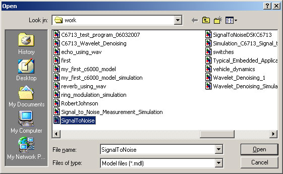
Opening SignalToNoise Model

Viewing the signaltonoise parent

The SignalToNoise parent is now displayed. Double-click on the Algorithm box.
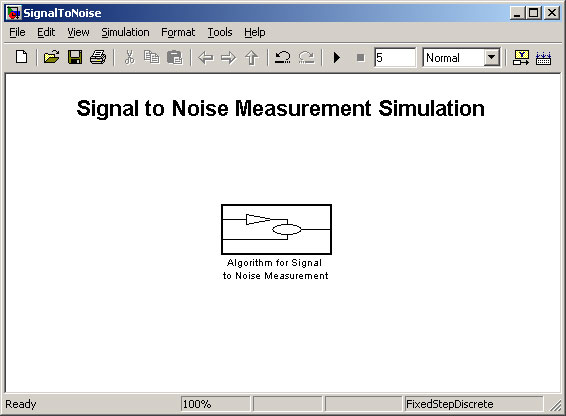
SignalToNoise Parent

Algorithm for signal-to-noise ratio measurement

The Signal-to-Noise Ratio algorithm is now displayed. Run the model.

Signal-to-Noise Ratio Algorithm

Output of the model

Run the model.

Algorithm Output

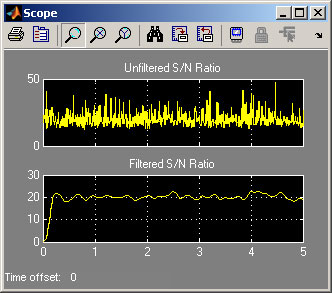
It will be seen that the output of the algorithm (“Unfiltered S/N”) varies from frame to frame. The next step is to fine-tune the algorithm parameters.

The model is run several times to determine the best values of the parameters:

  • To evaluate the algorithm accuracy for different frequencies
  • To determine the optimal frame length
  • To set the optimum delay time
  • To evaluate the effect of sampling frequency
  • To obtain a consistent algorithm output.

Evaluating the algorithm accuracy for different frequencies

Change the sine wave frequency from 500 Hz (default) to 1000 Hz then run the model several times. Make a note of the four different meter outputs (S/N Ratio from RMS Signals, Unfiltered S/N, Filtered S/N and Buffered).
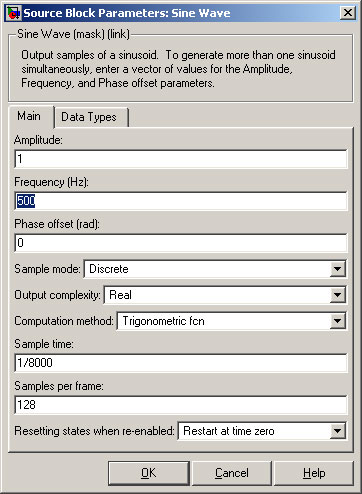
Changing the Sine Wave Frequency

Repeat using 1500Hz and 2000Hz.

Question: Does the input frequency of the Sine Wave have an effect on the accuracy of the algorithm? If it does, then it would be useful to put a digital filter at the input to the algorithm to limit the frequency band.

Sine wave 300 hz

Change the Sine Wave Frequency to 300Hz then run the model.

Get Jobilize Job Search Mobile App in your pocket Now!

Get it on Google Play Download on the App Store Now


Source:  OpenStax, From matlab and simulink to real-time with ti dsp's. OpenStax CNX. Jun 08, 2009 Download for free at http://cnx.org/content/col10713/1.1
Google Play and the Google Play logo are trademarks of Google Inc.

Notification Switch

Would you like to follow the 'From matlab and simulink to real-time with ti dsp's' conversation and receive update notifications?

Ask