| << Chapter < Page | Chapter >> Page > |

When a signal passes through a channel, it normally gets corrupted by channel noise. Various electronic components used in a transmitter or receiver may also cause additional noise. Noise reduction is an important aspect of any signal processing system. Lab 7 features noise reduction techniques using digital and analog filters. This section presents a simple technique to reduce high-frequency noise.
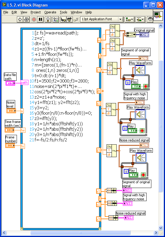
[link] shows the completed block diagram of a noise reduction system. Consider a speech signal sampled at 8 kHz. Add some high-frequency noise to this signal and then remove the high-frequency components in the frequency domain. Finally, move the signal back into the time domain using the inverse FT. Use the LabVIEW MathScript function wavread to read a wave file specified by the string Path and return the sampled data at a specified sampling rate. A
String Control
(Controls
→
Modern
→
String&Path
→
String Control) can be added to the input Path to provide the path name for the speech data file. Use two more controls named Time frame width and Frame number to extract a segment of the speech signal before computing Fourier transform. Add together three sine and cosine waves with frequencies of 3.5, 3 and 2.8 kHz to create a high-frequency noise. Then add a scaled version of the noise signal to the signal with the Scaling parameter set as a control. Compute the FT of the Noise added signal using the function
fft .
To remove the high-frequency noise components, use a simple lowpass filter by removing the frequency components over a certain threshold (50 percent, for example). After removing the high-frequency components, transform the signal back into the time domain using the function
ifft . To get a display of the absolute and centered frequency spectrum, use the functions abs and
fftshift . The signals are displayed in the time domain using the functions
Build Waveform and
Waveform Graph . To be able to hear the speech signals, use the function
Play Waveform
(Functions
→
Programming
→
Graphics&Sound
→
Sound
→
Output
→
Play Waveform) . Connect the time domain signals to this function via the while loop structure. Connect a
Boolean control
(Controls
→
Modern
→
Boolean
→
Push Button) to the loop control, which acts as a play switch for the sound signal. The signals are also displayed in the frequency domain using the functions
Bundle
(Functions
→
Programming
→
Cluster, Class&Variant →
Bundle) and
XY Graph
(Controls
→
Modern
→
Graphs
→
XY Graph) .

[link] shows the front panel of the system. Inside the Data File Path control, the location of the speech data file is specified. Three graphs for the Original signal, Noise added signal and Noise reduced signal are shown in both the time and frequency domains. Use the noise level control to allow setting the amount of noise added to the original signal. After running the program, click on the Play button next to each signal. Hear the Original Signal and the Noise added signal. Notice that an unpleasant high-pitched noise gets added to the signal. If the noise level is set more than 0.5, the Original Signal becomes very difficult to hear. Next, hear the Noise reduced signal, which is similar to the Original Signal. The Noise reduced signal is not exactly the same as the Original Signal because some high-frequency components are also removed along with the noise.

Notification Switch
Would you like to follow the 'An interactive approach to signals and systems laboratory' conversation and receive update notifications?