| << Chapter < Page | Chapter >> Page > |
An inductor is an electrical component that stores energy in the form of a magnetic field. In its simplest form, an inductor consistsof a wire loop or coil. Figure 2 depicts an inductor next to a coin to show its relative size and structure.
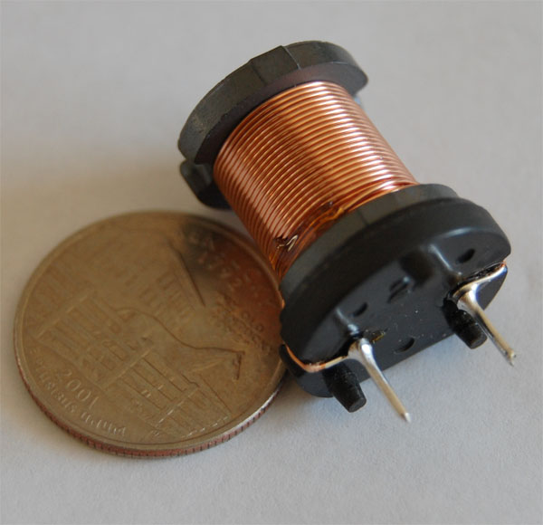
The inductance of the component is directly proportional to the number of turns present in the wire that makes up the coil. Inductance also depends on the radius of the coil and on the type of material around which the coil is wound. The standard unit of inductance is the Henry (H).
The schematic symbol for an inductor is shown in Figure 3.

A capacitor is an electrical device consisting of two conducting plates separated by an electrical insulator (the dielectric ), designed to hold an electric charge. Charge builds up when a voltage is applied across the plates, creating an electric field between them. Current can flow through a capacitor only as the voltage across it is changing, not when it is constant. Capacitors are used in power supplies, amplifiers, signal processors, oscillators, and logic gates.
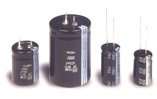
The standard unit of capacitance is the farad (F). Typical capacitance values are small. Common capacitors have values of capacitance that are expressed in units of microfarads (µF). Figure 4 shows a photograph of a several different capacitors.
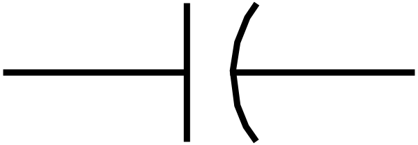
The standard symbol for a capacitor is shown in Figure 5.
In the case of electric circuits that are driven by a sinusoidally varying voltage source, the impedance serves to restrict the flow of current. Like the resistance, impedance is measured in ohms (Ω). However, the impedance differs from resistance in that the impedance is a complex quantity. Because the impedance is a complex quantity, we will represent the impedance as a complex number
The real part of Z as stated in equation (3) is R and the imaginary part is X .
Resistors, inductors and capacitors serve to contribute to the impedance present in a sinusoidally varying electric circuit. The impedance of a resistor is merely the value of its resistance.
The impedance of an inductor ( Z L ) can be easily computed via the relationship
The impedance of an inductor is measured in the units Ω. The term ω is equal to the angular frequency of the sinusoidally varying source voltage. Examination of equation (4) indicates that as the angular frequency increase, so too does the impedance of the inductor. At very high frequencies an inductor will essentially inhibit all flow of current through itself.
The impedance of a capacitor ( Z c ) is given by the equation
The impedance of a capacitance is measured in the units Ω. Once again, the term ω is equal to the angular frequency of the sinusoidally varying source voltage. Examination of equation (5) indicates that as the angular frequency increases, the impedance of the capacitor decreases. At very high frequencies a capacitor will behave as a short circuit. That is, its effect at very high frequencies is to allow current to flow through it in an unimpeded manner.
Just as resistors can be combined using series and parallel connections, so too can impedances. In the case of series connections, impedances are merely added. One distinction is that the addition is performed using complex arithmetic. Let us consider the RL circuit shown in Figure 6.
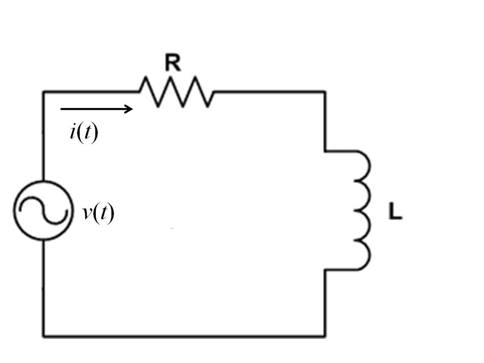
The series impedance is equal to the sum of the resistance with the impedance of the inductor. Suppose that for this circuit the value of R is 10 Ω and that the value for the inductance is 100 mH. Suppose that the frequency (ω) of the source voltage is 100 rad/sec. For this specification of values, we can compute the impedance of the series connection
The square of the magnitude of the impedance can be obtained by use of the complex conjugate.
So we calculate the magnitude of the impedance to be
An important property of AC circuits that contain an AC source voltage along with resistors, inductors and capacitors is that if the current i(t) will take the form of a sinusoid
The instantaneous value of the current is measured in Amps. The angular frequency of the current sinusoid (ω) will be the same as that of the sinusoid that represents the supply voltage. In addition, electric circuits involving resistors, capacitors and inductors will contribute to a change in the phase angle ( θ i ) of the current sinuosoid. In general the phase angle of the voltage sinusoid ( θ v ) will differ from that of the current sinusoid ( θ i ). Once again, the discussion of how the phase angle of the current can be computed will be deferred until our later discussion of trigonometry.
Once we know the magnitude of the impedance, we can use it to calculate the amplitude of the sinusoidally varying current, I max . This is accomplished by the following formula.
So the amplitude of the current is V max /141.7. It is interesting to note that this formula is similar to Ohm’s Law. The differences lie in the fact that the magnitude of the impedance appears instead of the resistance. Also, the amplitudes of the sinusoidally varying current and voltage appear.
The formula expressed above is useful in determining the amplitude of the current for a wide range of sinusoidally varying AC circuits. These circuits can combine resistors with inductors and capacitors to create a wide range of design options for electrical engineers. The following exercises illustrate the application of complex numbers to the analysis of AC circuits.
Consider the series RC circuit shown below
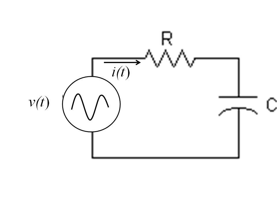
Suppose that the sinusoidally varying source voltage is given as

Notification Switch
Would you like to follow the 'Math 1508 (laboratory) engineering applications of precalculus' conversation and receive update notifications?