| << Chapter < Page | Chapter >> Page > |
This method constructs and returns a specific 3D surface in a 2D array of type double . The surface is identified by the value of an incoming parameter named switchCase . There are 14 possible cases. The allowable values for switchCase range from 0 through 13 inclusive.
The other two input parameters specify the size of the surface that will be produced in units of rows and columns.
The getSpatialData method begins in Listing 14 .
| Listing 14. Beginning of the getSpatialData method. |
|---|
private static double[][]getSpatialData(
int switchCase,int rows,int cols){double[][] spatialData =new double[rows][cols];switch(switchCase){ |
Listing 14 begins by creating a 2D array object of type double in which to store the surface.
Then Listing 14 shows the beginning of a switch statement that will be used to select the code to create a surface that matches the valueof the incoming parameter named switchCase .
Listing 15 shows the code that is executed for a value of switchCase equal to 0.
| Listing 15. Code for Case 0. |
|---|
case 0:
spatialData[0][0] = 1;break; |
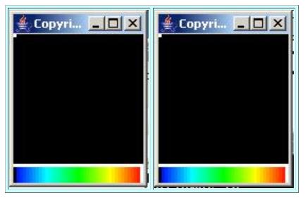
This case places a single non-zero point at the origin in the space domain. The origin is at the top-left corner. The surface produced by this case is shownin the leftmost image in Figure 5 . The non-zero value can be seen as the small white square in the top-left corner. In signal processing terminology,this point can be viewed as an impulse in space. It is well known that such an impulse produces a flat spectrum in wavenumber space.
| Figure 5. An impulse in space. |
|---|
 |
The rightmost image in Figure 5 shows the result of:
You can see the impulse as the small white square in the top-left corner of both images.
Because the wavenumber spectrum is flat, plots of the spectrum are completely featureless. Therefore, I did not include them in Figure 5 .
The numeric output shows that the final output surface matches the input surface to within an error that is less than about one part in ten to thefourteenth power. The program produces the expected results for this test case.
If you were to go back to the equations in Listing 2 and Listing 3 and work this case out by hand, you would soon discover that the computationalrequirements are almost trivial. Most of the computation involves doing arithmetic using values of 1 and 0. Thus, there isn't a lot of opportunity forcomputational errors in this case.
Now we are going to see a case that is more significant from a computational viewpoint. The input surface in this case will consist of a single impulse thatis not located at the origin in the space domain. Rather, it is displaced from the origin.
The wavenumber amplitude spectrum of a single impulse in the space domain should be flat regardless of the location of the impulse in the space domain.However, the real and imaginary parts of the wavenumber spectrum are flat only when the impulse is located at the origin in space.

Notification Switch
Would you like to follow the 'Digital signal processing - dsp' conversation and receive update notifications?